Continue to Site

Welcome to EDAboard.com

Welcome to our site! EDAboard.com is an international Electronics Discussion Forum focused on EDA software, circuits, schematics, books, theory, papers, asic, pld, 8051, DSP, Network, RF, Analog Design, PCB, Service Manuals... and a whole lot more! To participate you need to register. Registration is free. Click here to register now.

oscillations in LNA

Status
Not open for further replies.

Maitry

Junior Member level 1
Joined
Sep 17, 2020
Messages
16
Helped
0
Reputation
0
Reaction score
0
Trophy points
1
Activity points
127
Hello,

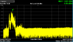
Please provide guidance on how to remove oscillations in LNA , as with the condition of DC on , input RF off, I found very high oscillations. I am using 2 MACOM MAAL-007304 LNA , individually they are working fine, there are no oscillations, but when provide DC to both, oscillations arise.

Please guide.
 

Hi,

most probably
* unsuitable PCB layout
* unsuitable power supply decoupling
* unsuitable circuit

--> schow your schematic and photos of your circuit (both sides) and/or the PCB layout.

Klaus
 

Each MAAL-007304 circuit have 25dB of gain, together they have more than 50dB of gain, which is a lot of gain for a 0.5GHz-3GHz amplifier.
When cascading two MAAL-007304 circuits have to rethink the interstage impedance matching network, which will be different than the inp/out matching network recommended in the datasheet by MACOM for a single chip.
Use the provided S-parameters and an RF simulator, and tune for a stable system between 0.5GHz and 3GHz (or maybe even more).
You can decrease a bit the combined gain of the circuit, to improve stability, because I don't think 50dB of gain is mandatory..


I agree with vfone, 50dB is too high for amplification.
Oscillations accur generally when a bad layout is used. Especially GND connections of MMIC LNAs, are very dangerous. They have to be carefully designed and GND must be very well maintained for LNA. Physical distance is also important and screening is absolutely critical..
 

Each MAAL-007304 circuit have 25dB of gain, together they have more than 50dB of gain, which is a lot of gain for a 0.5GHz-3GHz amplifier.
When cascading two MAAL-007304 circuits have to rethink the interstage impedance matching network, which will be different than the inp/out matching network recommended in the datasheet by MACOM for a single chip.
Use the provided S-parameters and an RF simulator, and tune for a stable system between 0.5GHz and 3GHz (or maybe even more).
You can decrease a bit the combined gain of the circuit, to improve stability, because I don't think 50dB of gain is mandatory..


Hello,

Thank you for your guidance.

Is it possible to optimize for stability via RF simulator using s2p file (as it is for the linear operation simulation) ?

Please guide.
 

MAAL-007304 is a low power linear amplifier so, s2p parameters should be fine for stability optimization.
 

Hi,

please calrify: do you use both amplifiers connected in series? (to increase gain)

Klaus
 

Hello,

There is a band pass filter in between both the LNA.
 

Hi,

in post#2 I asked for schematic, phitos, PCB layout.

I guess I know now why you don´t provide them.... ;-)

Klaus
 

Hello,

Thank you for your guidance.

Is it possible to optimize for stability via RF simulator using s2p file (as it is for the linear operation simulation) ?

Please guide.


Hello,

I have done the simulation using s2p file by cascading both MACOM LNA , The results are different than we expected, as stability k>1 for full band 0.5 to 2.3 GHz ( I have used the matching components as per recommended in datasheet for both LNA in simulation).

please guide.
 

Did you include the band pass in the simulation? If so, we can just guess that the real circuit has parasitic feedback from output to input which causes the instability.
 

yes , i have added bpf in simulation
 

in practical, with dc on , rf off condition, oscillations arise, is it possible to have issue in the bias lines?
 

In the real circuit, there can be parasitic coupling through shared supply lines, through box resonances etc. None of this is found by circuit simulation.
 

In the real circuit, there can be parasitic coupling through shared supply lines, through box resonances etc. None of this is found by circuit simulation.
Hello,

I have tried to provide biasing with different individual supply to both MACOM- LNA , but when provide DC is given to both one by one, oscillations arise with DC given to 2nd MACOM LNA. there are 0.1 uF bypass capacitors in the bias lines as per datasheet.
 

Show a photo of your layout and setup.

What is the oscillation frequency?
Have you checked if/where it is "hand sensitive" and changes when you touch DC lines?
 

Show a photo of your layout and setup.

What is the oscillation frequency?
Have you checked if/where it is "hand sensitive" and changes when you touch DC lines?
Hello,

Yes it is hand sensitive, it changes when I touch the DC lines. please check oscillations results. layout is same as eval board of macom lna.
 

Attachments

  • oscillations with dc on and rf off.png
    oscillations with dc on and rf off.png
    27 KB · Views: 242

I am using eval board of MACOM directly.
 

Eval board is for single MAAL-007304. We still don't know the complete setup.
 

Status
Not open for further replies.

Similar threads

Part and Inventory Search

Welcome to EDABoard.com

Sponsor

Back
Top