Eshal
Advanced Member level 1

- Joined
- Aug 29, 2012
- Messages
- 470
- Helped
- 16
- Reputation
- 32
- Reaction score
- 15
- Trophy points
- 1,298
- Location
- Nowhere :)
- Activity points
- 5,149
How are you all?
Experts my problem is regarding with Orcad 16.6. I have lite version.
I have a practical from digital electronics in which I am using flip flop, the edge triggered J K flip flop.
Can you tell which is the square wave generator to give the clock to the J K flip flop? I am using Vpulse. But I don't know how to set frequency in it. I want to use 1KHz and 5Vp-p. And there are several more parameters which I don't know. What should be V1, V2. V1=0v and V2=5v. Is it?
What is TD and should I put in the value of TD?
What is TR and should I put in the value of TR?
What is TF and should I put in the value of TF?
PW is the pulse width but should I put in the value of PW?
What is PER and should I put in the value of PER?
Where is frequency parameter?
And why doesn't my simulation button able to press? It can't be press. What should I do to press it?
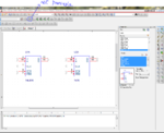
The picture is also attached below. There are two J K flip flops are shown. Which one should I use? In the experiment I have given with 74LS76 but 7476 seems same as 74LS76. And where is the Vcc pin and GND pin in it? How to supply Vcc and GND to the IC?

Thank you sir.
Experts my problem is regarding with Orcad 16.6. I have lite version.
I have a practical from digital electronics in which I am using flip flop, the edge triggered J K flip flop.
Can you tell which is the square wave generator to give the clock to the J K flip flop? I am using Vpulse. But I don't know how to set frequency in it. I want to use 1KHz and 5Vp-p. And there are several more parameters which I don't know. What should be V1, V2. V1=0v and V2=5v. Is it?
What is TD and should I put in the value of TD?
What is TR and should I put in the value of TR?
What is TF and should I put in the value of TF?
PW is the pulse width but should I put in the value of PW?
What is PER and should I put in the value of PER?
Where is frequency parameter?
And why doesn't my simulation button able to press? It can't be press. What should I do to press it?
The picture is also attached below. There are two J K flip flops are shown. Which one should I use? In the experiment I have given with 74LS76 but 7476 seems same as 74LS76. And where is the Vcc pin and GND pin in it? How to supply Vcc and GND to the IC?

Thank you sir.

