Continue to Site

Welcome to EDAboard.com

Welcome to our site! EDAboard.com is an international Electronics Discussion Forum focused on EDA software, circuits, schematics, books, theory, papers, asic, pld, 8051, DSP, Network, RF, Analog Design, PCB, Service Manuals... and a whole lot more! To participate you need to register. Registration is free. Click here to register now.

Opto Isolator Example

Status
Not open for further replies.

theguy

Junior Member level 1
Joined
Jan 19, 2012
Messages
15
Helped
1
Reputation
2
Reaction score
0
Trophy points
1,281
Activity points
1,406
I have a 4N25 and I want to create a 5V out @ 1Hz across a 50ohm load.

Here is my first attempt. When I look at it, I don't think it will provide what I need. I haven't ordered the parts yet so I wanted to get a second opinion before I do.
opto-cirucit.jpg


The 5v 1PPS is the 1PPS from a Garmin GPS receiver. I assume connecting the Garmin 1PPS output to the LED as I did would be safe.
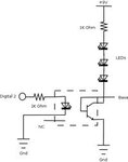
 

This circuit what you provide are not isolated not even opticaly isolated.

If you whant 5V at 1sec on optocoupler trasnsitor side you should make 5V power source on that side, and on LE diode side of optocoupler you should make some oscilator that give power to LED every 1sec.

Pay attention to limit current for optocoupler on both side, acording manufacturer datasheets for that optocoupler.

Optocoupler on its LE diode side will draw some current needed for operation (about few miliamp, example 5mA to 50mA). Can you draw that current from Garmin?

You can always use phototransistor to sense light form Garmin LE diode and turn some transistor which will turn some relay. This will be completely separated from Garmin and no need for any opening of device or such things. No power consuption for LE diode from Garmin. This will be completly separate device from garmin.


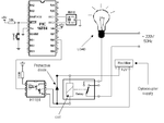
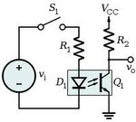
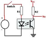
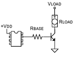
There is some examples :

2images.jpg

16.gif

images.jpg

in_opto.gif

typical-optocoupler-circuit.jpg
 
Last edited:

This circuit what you provide are not isolated not even opticaly isolated.

If you whant 5V at 1sec on optocoupler trasnsitor side you should make 5V power source on that side, and on LE diode side of optocoupler you should make some oscilator that give power to LED every 1sec.

Pay attention to limit current for optocoupler on both side, acording manufacturer datasheets for that optocoupler.

Optocoupler on its LE diode side will dwar some current needed for operation (about few miliamp, example 5mA to 50mA). Can you draw that current from Garmin?

You can always use phototransistor to sense light form Garmin LE diode and turn some transistor which will turn some relay. This will be completely separated from Garmin and no need for any opening of device or such things. No power consuption for LE diode from Garmin. This will be completly separate device from garmin.


There is some examples :

View attachment 67717

View attachment 67718

View attachment 67719

View attachment 67720

View attachment 67721

My goal is to be able to drive the 50ohm load as this is an input into another system. I don't care too much about keeping them isolated.
 

My goal is to be able to drive the 50ohm load as this is an input into another system. I don't care too much about keeping them isolated.

One question you whant to pull power from Garmin, for 50R ?

You must know that LED in Garmin have limited current, I supose to 2mA, if you attach 50R in serie with that, you will decrease current and get nothing.


50R load tells nothing if you dont know voltage.

Example :

If you put 50R on 5V current is 5V/50R = 0,1A (100mA)
If you put 50R on 2V current is 2V/50R = 0,04A (4mA)


We gues Garmin use 2mA LED 3,7V.
3,7V / 1500R = 0,0024A (2,4mA)

If you put additional 50R in serie on that 2,4mA (serie with 1500R) you will get 2,3mA.
But there is another problem, you say ok there is enough current, but you should know that LED have voltage level needs to operate. You should increase voltage level if you whant LED to light in serie.
 
Last edited:

One question you whant to pull power from Garmin, for 50R ?

You must know that LED in Garmin have limited current, I supose to 2mA, if you attach 50R in serie with that, you will decrease current and get nothing.


50R load tells nothing if you dont know voltage.

Example :

If you put 50R on 5V current is 5V/50R = 0,1A (100mA)
If you put 50R on 2V current is 2V/50R = 0,04A (4mA)


We gues Garmin use 2mA LED 3,7V.
3,7V / 1500R = 0,0024A (2,4mA)

If you put additional 50R in serie on that 2,4mA (serie with 1500R) you will get 2,3mA.
But there is another problem, you say ok there is enough current, but you should know that LED have voltage level needs to operate. You should increase voltage level if you whant LED to light in serie.

Your first example is correct. The goal is to input the Garmin 1pps @5V into the 50ohm input. Since the garmin cannot provide the current, I wanted to buffer the garmin 1pps signal. I need the 1pps input into the 50ohm system to be in phase with the the garmin 1pps because it will be used as a sync for the system.

If you look at the circuit I provided, the Vout is the 5V 1pps that will be input into my system which has a 50ohm input.
 

Your first example is correct. The goal is to input the Garmin 1pps @5V into the 50ohm input. Since the garmin cannot provide the current, I wanted to buffer the 1pps signal. I need the 1pps to be in phase as the 1pps will be a sync for the system.

If you look at the circuit I provided, the Vout is the 5V 1pps that will be input into my system which has a 50ohm input.

Garmin should have 3,7V lithium battery, did you check 5V voltage on garmin LED ? :shock:
LED should not have over 2V if green,red,orange (signal showing, or such things), for white led voltage is higher about 3V or over.

If you need synch with garmin led you can do what I proposed in post #2. To use optocoupler on right way, or to use completely separate circuit with phototransistor. In both way you will get synch of LED light and duration of signal.

If you plan to pull power from Garmin I dont recommend that. You should have 3,7V not 5V in device, and my suggestion is to use external power for your external circuit.

If zou plan to consupt power from 3,7V from Garmin then 3,7V / 50R = 74mA. You should know that will shorted battery cycle and working hour of Garmin, or can produce malfunction of Garmin.
 
Last edited:

Garmin should have 3,7V lithium battery, did you check 5V voltage on garmin LED ? :shock:
LED should not have over 2V if green,red,orange (signal showing, or such things), for white led voltage is higher about 3V or over.

If you need synch with garmin led you can do what I proposed in post #2. To use optocoupler on right way, or to use completely separate circuit with phototransistor. In both way you will get synch of LED light and duration of signal.

If you plan to pull power from Garmin I dont recommend that. You should have 3,7V not 5V in device, and my suggestion is to use external power for your external circuit.

If zou plan to consupt power from 3,7V from Garmin then 3,7V / 50R = 74mA. You should know that will shorted battery cycle and working hour of Garmin, or can produce malfunction of Garmin.

Perhaps I should start over.

I have a Garmin GPS receiever that has an electrical 5V 1PPS signal (there are no LEDs). I plan to power the garmin using a 5V power supply. I had planned to use a 4N25 opto isolator as a buffer for this 1PPS so that I can input it into another system that has a 50ohm input. The Garmin 1PPS 5V electrical signal cannot handle the required 100mA needed for the 50ohm input which is why I need a buffer. Of course I am open to other options, but I was looking for something simple and would have preferred using an Op-Amp, but I had trouble finding an Op-Amp that could provide the 100mA needed.
 

As far as I understand, you don't intend isolation, so why using an opto isolator? There's also no need of an OP to buffer a digital signal. A complementary transistor switch (NPN+PNP) will do.
 

From which part of Garmin circuit you plan to take signal ?

4N25 cant be buffer its just signal opto isolator.

If you plan to use optocoupler for optoisolation you can see examples from given examples.

Pulling 5V from Garmin signal to power external circuit is not good.
 
Last edited:

As far as I understand, you don't intend isolation, so why using an opto isolator? There's also no need of an OP to buffer a digital signal. A complementary transistor switch (NPN+PNP) will do.

Could you recommend a part and configuration?
 

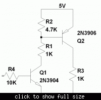
To drive out 100 mA, we should have a PNP output stage. You can use any NPN/PNP small signal transistors for the circuit.


To drive out 100 mA, we should have a PNP output stage. You can use any NPN/PNP small signal transistors for the circuit.


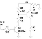
So then If I connect the 50ohm load to the VE of Q2, how can VE switch to 0V? I added the connection to my systems, GPS Garmin (that provides the 1PPS @ 5v), and Simulator (50ohm load that receives the 5V 1PPS)

complementary_transistor_pair.jpg
 

Yes, in fact I won't expect a good effect from connecting the 50 ohm instrument input to the 5 V power supply.

Obviously, the collector terminal of Q2 is the circuit output and R3 a basic load. The 50 load woudl be connected in parallel to R3.
 

Yes, in fact I won't expect a good effect from connecting the 50 ohm instrument input to the 5 V power supply.

Obviously, the collector terminal of Q2 is the circuit output and R3 a basic load. The 50 load woudl be connected in parallel to R3.

Thank you, I think I understand now. I will order the parts needed. I will be sure to test on an OScope before I connect to equipment to make sure I have everything connected correctly.

I'll return with my results. Thank Again.
 

Status
Not open for further replies.

Part and Inventory Search

Welcome to EDABoard.com

Sponsor

Back
Top