Continue to Site

Welcome to EDAboard.com

Welcome to our site! EDAboard.com is an international Electronics Discussion Forum focused on EDA software, circuits, schematics, books, theory, papers, asic, pld, 8051, DSP, Network, RF, Analog Design, PCB, Service Manuals... and a whole lot more! To participate you need to register. Registration is free. Click here to register now.

Operational Amplifier Question in CMFB stability

Status
Not open for further replies.

amr.walid

Newbie level 2
Joined
May 31, 2012
Messages
2
Helped
0
Reputation
0
Reaction score
0
Trophy points
1,281
Activity points
1,294
Hi All
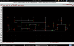
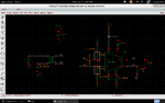
I have a problem that I want to design Op-Amp and its bias set as shown in the attached figures so When I vary the resistors of the bias the CMFB loop vary also so I can't get a defined Phase Margin across all values of resistor.
Please I want an answer to this effect that I can't understand it.
Thanks in advance
 

Attachments

  • circuit&CMFB.png
    circuit&CMFB.png
    41.3 KB · Views: 121
  • Total_system.png
    Total_system.png
    42.6 KB · Views: 107

I guess the problem is created by an unrealistic high common mode source impedance which won't be found in a real world amplifier setup.

You should add a small amount of common mode capacitance, e.g. from transformer center tap to ground.
 
Thanks for your help but mainly my problem is that I can't understand how these common mode bias resistors can affect my CMFB loop also this loop hasn't any relation with these two resistors.
 

Surely they are related.

Please consider what happens if the input stage is driven by a high common mode impedance. Also remember that MOSFETs have finite input impedance at higher frequencies.

How about sketching an equivalent circuit of the common mode amplifier and feedback path?
 
Status
Not open for further replies.

Part and Inventory Search

Welcome to EDABoard.com

Sponsor

Back
Top