Continue to Site

Welcome to EDAboard.com

Welcome to our site! EDAboard.com is an international Electronics Discussion Forum focused on EDA software, circuits, schematics, books, theory, papers, asic, pld, 8051, DSP, Network, RF, Analog Design, PCB, Service Manuals... and a whole lot more! To participate you need to register. Registration is free. Click here to register now.

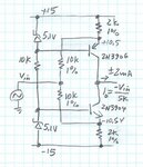
Operation of attached cascode current souce circuit.

Status
Not open for further replies.

zoulzubazz

Member level 5
Member level 5
Joined
Apr 26, 2012
Messages
87
Helped
3
Reputation
6
Reaction score
3
Trophy points
1,288
Visit site
Activity points
2,040
Hey guys,

I found the attached current source circuit in the following link to a forum, post number 7.

https://cr4.globalspec.com/thread/88515/constant-current-source-with-1-MHz-frequency-problem

Unfortunately i cant figure out how it works, could someone shed some light on the circuits working or some resources which would help understand its working. Thanks very much.

bipolar-current-source.JPG
 

The 5.1V zeners has low impedance and fixes the Vb and thus Ve voltages with 0.65V drop for Vbe.
Thus the voltage drop on the emitter resistors determines current limit.
The 2k R's supply current and Vin removes current thus modulating the output to load current as a voltage controlled current source
 
thanks mate, is there any reason power transistors cannot be used in this circuit to deliver a current of about 1A at about 10MHz to 15 MHz?
 

thanks mate, is there any reason power transistors cannot be used in this circuit to deliver a current of about 1A at about 10MHz to 15 MHz?

If the load resistance is 5K, Vin will be so 5kV ??? Are you sure that ???
 

Status
Not open for further replies.

Part and Inventory Search

Welcome to EDABoard.com

Sponsor

Back
Top