pforpashya
Member level 2

- Joined
- Jan 12, 2010
- Messages
- 42
- Helped
- 0
- Reputation
- 0
- Reaction score
- 0
- Trophy points
- 1,286
- Location
- जगा व जगू द्या
- Activity points
- 1,609
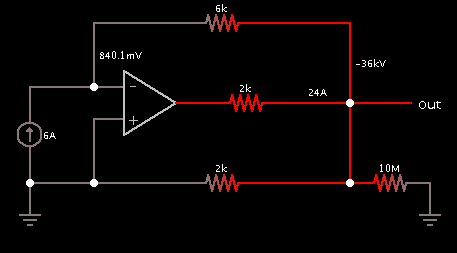
I don't know how to deal with this particular problem. please tell me how to approach and solve to get correct answer.
figure is given below.
thanks in advance
https://obrazki.elektroda.pl/3484186500_1359702297.jpg
figure is given below.
thanks in advance
https://obrazki.elektroda.pl/3484186500_1359702297.jpg