SBTECH
Newbie level 6
- Joined
- Feb 17, 2010
- Messages
- 12
- Helped
- 0
- Reputation
- 0
- Reaction score
- 0
- Trophy points
- 1,281
- Location
- Istanbul, Turkey
- Activity points
- 1,390
Hi ,
I am reading a temp sensor data between 0-10Volts with an ADC capable of reading 0-2.5V.
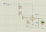
So I made a voltage divider and a voltage follower with lm 324 opamp which is sourced by 9V single supply. I am not experienced about analog circuits and i made this test circuit in the attachment .
When i connect no loads to the output i measure 0 volts , when i connect 120 ohm to the output through ground i measured 0.55 V on the output. I measure 2.25 volts between non inverting input and ground. but at the common point (output and inverting input point ) to the ground i dont measure the same voltage. It must be same according to theory of opams.
I tried to put 5 ohms and my opamp overheated itself , now no matter i connect anything to its inputs or outputs,when i just power it with 9V it overheats itself , i think its broken now.
So what should i do to make this voltage follower work . I always had so many problems with opamps , i wanna solve my problems with them this time.. Could you share ideas to make this voltage follower work ?
Many thanks ..

Last edited: