Continue to Site

Welcome to EDAboard.com

Welcome to our site! EDAboard.com is an international Electronics Discussion Forum focused on EDA software, circuits, schematics, books, theory, papers, asic, pld, 8051, DSP, Network, RF, Analog Design, PCB, Service Manuals... and a whole lot more! To participate you need to register. Registration is free. Click here to register now.

[SOLVED] Opamp doesn't stop at 0

Status
Not open for further replies.

Soribot

Newbie
Joined
Nov 18, 2020
Messages
3
Helped
0
Reputation
0
Reaction score
0
Trophy points
1
Activity points
27
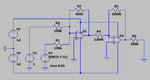
Hello, i'm an electrical engineering student and i need some help. I have a homework about OpAmps in LTSpice and i don't know how to control the output voltage of the second OpAmp to be between 0V and 12V. The teacher didn't give us any clues and in classroom we only did this kind of problems for DC input voltage. I put the resistences using some formulas given by my teacher and the inputs of the sources is the ones in the photo.
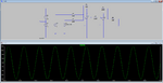
 

Attachments

  • AICICIAISNODASNDOIBN.png
    AICICIAISNODASNDOIBN.png
    34.2 KB · Views: 116

Think of the basic operation starting with U1. I am assuming you have
had basic operation of opamp when feedback is applied to it, how it
operates on signal you then feed to it, what its closed loop G (Gain) is ...

By superposition take just the sine, which is symmetrical about ground,
so what does the opamp output look like just feeding sine into circuit ?
What is the G, what are the differences between sine in and what it looks
like out of U1 circuit ?

Now by superposition, what does the amp circuit do to the DC V3 ?

What is the output due to V3 ? What does V3 due to the combined signal ?

So these two signals are summed because of the operation of feedback.
You can intuit that because what is the V at inverting input to opamp with
feedback and its non inverting input grounded ? Thats key to rapid simple
evaluation of opamp circuits. Keep in mind when visualizing current flow
no appreciable current flows in or out of opamp input terminals. Note
advanced design has to consider even these tiny currents, but for now
ignore. So what can we say about the current thru input R and fdbk R ?
That tells you what Vout has to be to insure what about the relationship
between circuit input current and fdbk current thru R fdbk...

Then you follow all this with a inverting opamp with a G = ?

OpAmps, amps with lots of G and differencing inputs one of the best
components we have as engineers to solve signal processing needs.


Regards, Dana.
 
Last edited:

You want the sine output to be scaled to min=0, max=12, or the shown sine clipped at 0V?
 
You want the sine output to be scaled to min=0, max=12, or the shown sine clipped at 0V?
The requirement was to convert, using the two opamps, the signal from 2 sources to a positive one, ranging from 0V(min) to 12V(max). But now i figured it out with the help of danadakk. Thanks anyway for the interest <3
 

Think of the basic operation starting with U1. I am assuming you have
had basic operation of opamp when feedback is applied to it, how it
operates on signal you then feed to it, what its closed loop G (Gain) is ...

By superposition take just the sine, which is symmetrical about ground,
so what does the opamp output look like just feeding sine into circuit ?
What is the G, what are the differences between sine in and what it looks
like out of U1 circuit ?

Now by superposition, what does the amp circuit do to the DC V3 ?

What is the output due to V3 ? What does V3 due to the combined signal ?

So these two signals are summed because of the operation of feedback.
You can intuit that because what is the V at inverting input to opamp with
feedback and its non inverting input grounded ? Thats key to rapid simple
evaluation of opamp circuits. Keep in mind when visualizing current flow
no appreciable current flows in or out of opamp input terminals. Note
advanced design has to consider even these tiny currents, but for now
ignore. So what can we say about the current thru input R and fdbk R ?
That tells you what Vout has to be to insure what about the relationship
between circuit input current and fdbk current thru R fdbk...

Then you follow all this with a inverting opamp with a G = ?

OpAmps, amps with lots of G and differencing inputs one of the best
components we have as engineers to solve signal processing needs.


Regards, Dana.
Thanks a lot Dana, i didn't understand everything you said :), but i did get the idea of trying the sources alone, and i got the flick amd understood how do they affect each other. Thanks again a lot, you the best.
 

Why do you spread the parts so far apart that the simple schematic is the size of my neighborhood?
I cropped it a little but R2 can be directly connected to the -input of U1 then the parts above it can be pushed down.
 

Attachments

  • two opamps.png
    two opamps.png
    14.4 KB · Views: 113

If you have Matlab or equivalent you can do a simple model and play with
its internal G and feedback factor, the ratio of the two resistors.

Note system is given 1 V to amplify, the constant block to left.

1605833111360.png


So if you look at above I set internal K (gain) at 1, and fdbk factor at .1 (feed 10% back). You can see
that the output is not very accurate, and that the differential input to OpAmp is large. So one
becomes suspicious that low K inside OpAmp not very appealing.

Now lets set K to 100,000 (typical OpAmp these days).

1605833049830.png


Several observations

1) Now overall G of whole simulation is 10, which is 1 / fdbk factor. Also the differential input
into OpAmp is very tiny. There is a term in industry, "virtual ground", that basically says an OpAmp
with - fdbk, fdbk back to inv input, results in that inv input virtually at same V with non inv input. If non
inv input was connected to ground then the inv input would also be close to ground. So if we connect
a summer like this -

1605831901911.png


So the virtual ground allows one to sum inputs without one input affecting the
other. Above the current of any input is set just by the input V and its R, the
other inputs do not affect each other. Then each input current is summed with
the others and flows thru fdbk R to produce a summed output.

Note no appreciable current flows into / out of the opamp inputs. In high performance
systems there is some, and causes errors, but for this discussion its essentially zero.

You can play with OpAmp internal K and the fdbk factor and observe that with
high K you get predictable output. Note G thru whole system is 1 / fdbk factor.
So for a fdbk factor of .1 overall system G = 10.

Also notice now with large K the G thru the whole system is suspiciously only a f(fdbk factor).
Its no longer a f(K) of the actual amplifier. fdbk factor is the ratio of the R's. So G is as
accurate as just the R's, or very close to it.

Early in electronics amps where cascades of one stage transistor amps, and transistor
K (for transistors gain normally called beta or alpha) varied all over the map. And to get
high G thru system you had to cascade many stages. Temperature performance due to
component changes and supply voltage variations caused significant performance vari-
ations. So designs had, compared to today, low performance and stability.

- feedback improves systems, original paper by Black at Bell Labs.


Positive fdbk is also used to achieve other characteristics in opamp circuits, thats a topic for another day.

Lastly this whole discussion is DC performance, AC is a whole other topic and also
quite interesting.


Regards, Dana.
 

Attachments

  • 1605831281625.png
    1605831281625.png
    57.7 KB · Views: 120
  • 1605831539845.png
    1605831539845.png
    58.2 KB · Views: 103
Last edited:

Hi,

At a guess, you should bias the non-inverting pin of the second amplifier (inverting) to maybe 4V above ground; might also need to re-scale gain to fit the 0V to 12V output.
 

Hi,

No promises this will work, I only did quick calculations, I'm assuming V3 is a permanent input, that V4 goes fron 0V to +2V, and am unsure if my added bias voltage should be positive or negative. Not able to simulate it or breadboard it just yet, either.

R1 = 200k
R2 = 100k
R3 = 400k
R4 = 400k
R5 = 1.2M
(R6 = 100k)
U2 IN+ input: Vref (Vbias) = + (or -) 3V

I used/tried to use this formula for a single-supply inverting op amp with a bias voltage so it may not work for a dual-supply circuit:

Vout = (-Vin * (R5/R4)) + (((R4 + R5) /R4) * Vref)

Assuming: U1 Vout is either -4V (from +1V V3 input + 0V from V4), or it is -8V (-4V + -4V) U2 Vout should go from 0V to +12V. Unless I've got some calculation polarities wrong, hope not.
 

Status
Not open for further replies.

Part and Inventory Search

Welcome to EDABoard.com

Sponsor

Back
Top