Continue to Site

Welcome to EDAboard.com

Welcome to our site! EDAboard.com is an international Electronics Discussion Forum focused on EDA software, circuits, schematics, books, theory, papers, asic, pld, 8051, DSP, Network, RF, Analog Design, PCB, Service Manuals... and a whole lot more! To participate you need to register. Registration is free. Click here to register now.

Opamp circuit to be used with Atmega16 microcontroller

Status
Not open for further replies.

amanpreetk

Junior Member level 2
Joined
Sep 9, 2014
Messages
21
Helped
0
Reputation
0
Reaction score
0
Trophy points
1
Visit site
Activity points
164
How can I design an opamp circuit to amplify 2.5-3.5 volts voltage range to 0-5 volts, to be supplied to ADC of ATMEGA16? Which opamp should I use?
 

You already can supply 2.5v-3.5v to the ADC of the atmega16, but if you need to amplify the voltage difference you can use a cheap OpAmp like LM358 or so.
 

Hi,

your input voltage range is 2.5 ... 3.5V, this makes a difference of 1V
Your output range is 0...5V, this makes a difference of 5V.

Gain = dUout/dUin = 5V/1V = 5

Now you can use a simple non inverting opamp circuit with gain = 5

Lets call the upper (feedback) resistor "RF" and the resistor to GND = "RG"

Now you need to compensate the input offset of 2.5V:
Here you may add a third resistor from -Vin to 5V (i hope this is your VCC). Lets call this pullup resistor = RU.

For gain calculations one must calculate as if RU is in parallel to RG

So the adjusted formula for RF is: RF = (gain -1) x 1/(1/RG + 1/RU) = 4 / (1/RG + 1/RU)

To achieve Vout =0V @ Vin = 2.5V the following formula must be true: RU = 1 / (1/RF + 1/RG)

combining both formula gives RF = RG * 3 / 2

Combining this in one of the above formula gives RU = RG = 0.6

Now i choose RG to be 20k0
then RU = 12k0
and RF = 30k0.

You need an RR output OPAMP, supplied with 0V and 5V.
Keep in mind, that even RR output opamps have a small dropout voltage to the rails.

Klaus
 

    V

    Points: 2
    Helpful Answer Positive Rating
Hi,

your input voltage range is 2.5 ... 3.5V, this makes a difference of 1V
Your output range is 0...5V, this makes a difference of 5V.

Gain = dUout/dUin = 5V/1V = 5

Now you can use a simple non inverting opamp circuit with gain = 5

Lets call the upper (feedback) resistor "RF" and the resistor to GND = "RG"

Now you need to compensate the input offset of 2.5V:
Here you may add a third resistor from -Vin to 5V (i hope this is your VCC). Lets call this pullup resistor = RU.

For gain calculations one must calculate as if RU is in parallel to RG

So the adjusted formula for RF is: RF = (gain -1) x 1/(1/RG + 1/RU) = 4 / (1/RG + 1/RU)

To achieve Vout =0V @ Vin = 2.5V the following formula must be true: RU = 1 / (1/RF + 1/RG)

combining both formula gives RF = RG * 3 / 2

Combining this in one of the above formula gives RU = RG = 0.6

Now i choose RG to be 20k0
then RU = 12k0
and RF = 30k0.

You need an RR output OPAMP, supplied with 0V and 5V.
Keep in mind, that even RR output opamps have a small dropout voltage to the rails.

Klaus


Thank you for your help. :)
Can you suggest me any specific RR output opamp that will be perfect for my circuit??
 

Hi,

try LMV321, or LMV358 (double), LMV324 (quad)

they should be cheap.

Klaus
 

    V

    Points: 2
    Helpful Answer Positive Rating
Hi,

try LMV321, or LMV358 (double), LMV324 (quad)

they should be cheap.

Klaus

Hi,
Thanks a lot for your suggestions. They really are helping me to clear my concepts.
I tried using the above mentioned opamps but i'm not getting the required output. With 2.5V - output is 3.12V
and with 3.5V - output is 3.14V ? Can you still help me with my problem?
 

Hi,

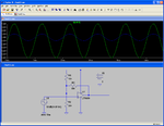
here schematic and simulation.

OP_SIM.png

Blue = input
green = output

LMV358 is not in library, so i used another RR output OPAMP

Klaus
 
Hi,

here schematic and simulation.

View attachment 109876

Blue = input
green = output

LMV358 is not in library, so i used another RR output OPAMP

Klaus
opp.JPGopp1.JPG

This is what I did..and my output does not reach exact 0 volts on input as 2.5v or 5 volts for 3.5v as input. And moreover if i don't apply 1k ohm resistor with the input voltage, the proteus gives error as - "Gmin stepping failed" ,
"Source step failed" and "Too many iterations with convergence" and hence, due to this error simulation dos not start.
 

Hi,

This is what I did..and my output does not reach exact 0 volts on input as 2.5v or 5 volts for 3.5v as input
As i already mentioned:
Keep in mind, that even RR output opamps have a small dropout voltage to the rails.

Going to the limits of an OPAMP (0V, 5V) or an ADC or a DAC is never a good idea, because with all devices they have "physical limits". This may be because one can not produce zero ohmic FETs, or infinite ohmic signal paths.
There are alsol design problems like offset errors, gain errors....

Even if you input 0.000V to an ADC it is not sure that it shows 0 LSB on the digital side.

But you use a microcontroller and you can write simple software to mange all these things.

*******
And moreover if i don't apply 1k ohm resistor with the input voltage, the proteus gives error as
Thats a simulation problem, not in reality.

*******

Klaus
 
  • Like
Reactions: amanpreetk

    amanpreetk

    Points: 2
    Helpful Answer Positive Rating
    V

    Points: 2
    Helpful Answer Positive Rating
Apparently, the OP model has a built-in offset voltage of 4 mV, resulting in 2.54 instead of ideal 2.5 V output with 3V input (gain of 10). That's in the order of magnitude which can be expected in the real circuit. If this is already too much, you have to choose expensive precision OPs and 0.1% resistor tolerance or better. Or perform an adjustment in software, as suggested.
 

    V

    Points: 2
    Helpful Answer Positive Rating
Be careful with the LM358 supply; it reachs the negative rail but is 1.5v under the positive one; supply it with 12V and calculate it to get 5V maximum at the output. You can use zeners to protect the MCU ADC input.
 

Hi,

LM_V_358 is the RR version of the classic LM358.

Input is RR
Output is RR
Offset voltage typ. Is 0.1mV
Outputs should go about 50mV to the rails

So i expect better quality than the simulation shows. It should work fine.

Klaus
 

    V

    Points: 2
    Helpful Answer Positive Rating
So i expect better quality than the simulation shows. It should work fine.
Typical offset voltage is about half the amount shown in the simulation, but maximum value is higher. In so far it's a realistic result. Expecting no offsets means ignoring real component behaviour.
 

Status
Not open for further replies.

Similar threads

Part and Inventory Search

Welcome to EDABoard.com

Sponsor

Back
Top