Continue to Site

Welcome to EDAboard.com

Welcome to our site! EDAboard.com is an international Electronics Discussion Forum focused on EDA software, circuits, schematics, books, theory, papers, asic, pld, 8051, DSP, Network, RF, Analog Design, PCB, Service Manuals... and a whole lot more! To participate you need to register. Registration is free. Click here to register now.

OPamp as a differential amplifier issue

Status
Not open for further replies.

RenesasT

Full Member level 2
Joined
Mar 11, 2016
Messages
149
Helped
0
Reputation
0
Reaction score
0
Trophy points
16
Activity points
1,330
Hi everyone,

Hope you guys are doing well.

I am trying to meaure the current through the motor using sense resistor of 10mohm.

I am using LM324 as a differential Op-amp.

The circuit description is as follows,

1) The sense resistor is connected in between 12V positive supply and motor . It means I am measuring the current at higher side.

2) The 12V positive side sense resistor is connected to non inverting terminal of Op-amp using 1K resistor.

3) The motor side sense resistor point is connected to inverting terminal of Op-amp using 1K resisitor.

4) The feedback resistor and the resitor at non inverting terminal to Gnd is 4.7K.

5) The LM324 is supplied with single supply of 5V I did not able to measure the current. Then I used single 12V supply then also I did not able to measure the current.

Please help me.
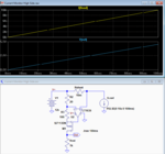
 

Hi,

a schematic - even hand drawn - is more informative than a lot of words.

Please next time give a detailed error description!

One thing is rather obvious:

The voltage at the non inverting input is 12V * 4k7 / (4k7 + 1k). Which is about 10V
Read datasheet about "Common mode input voltage range".
--> It says your LM324 need a supply voltage of more than 10V + 1.5V = 11.5V
5V supply surely won´t work.


****
Another thing to consider:
The motor current may be noisy. Please decide which upper frequency you are interested in. Then use a low pass filter to suppress all frequencies above this limit.
Best if you do this at the OPAMP input.

****

I recommend to use free simulation software like LTspice.

Klaus
 

    V

    Points: 2
    Helpful Answer Positive Rating
Yes I think Klauss nailed the main problem: your inputs exceed their input current range.

I suggest you consider a 'current sense amplifier' or 'high side current sense amplifier'. There are many parts which are designed to solve this problem and they'll run off 5V while monitoring 12V happily.


A quick fix would be two more resistors. Like 500, between the opamp +/- inputs and GND. If you calculate or simulate this I think you'll see this will divide down the sensed signals into the acceptable common mode input range of your amplifier while having no effect on gain (perhaps unintuitively). This has a negative impact on performance for a few reasons but it might get things working for you.
 

If you want to measure the high side current, then it's best to use a rail-rail op amp powered by the motor supply voltage.
The circuit below is typically used for high-side current measurement as it avoids the common-mode error of a standard differential amp circuit caused by resistor mismatch.

What's the maximum motor current you want to measure?

Capture.PNG
 

Status
Not open for further replies.

Part and Inventory Search

Welcome to EDABoard.com

Sponsor

Back
Top