Continue to Site

Welcome to EDAboard.com

Welcome to our site! EDAboard.com is an international Electronics Discussion Forum focused on EDA software, circuits, schematics, books, theory, papers, asic, pld, 8051, DSP, Network, RF, Analog Design, PCB, Service Manuals... and a whole lot more! To participate you need to register. Registration is free. Click here to register now.

OPAMP 2-stages design problems

Status
Not open for further replies.

ldhung

Member level 3
Joined
Jul 26, 2004
Messages
64
Helped
0
Reputation
0
Reaction score
0
Trophy points
1,286
Activity points
435
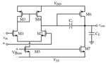
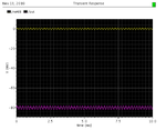
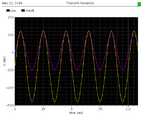
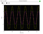
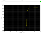
I designed an opamp unbuffered 2 stages, but there are the shifts between input and output. Please help me to adjust the output has the same offset is zero as input.
Please see the photos for more details.
Thanks
 

Attachments

  • opamp.png
    opamp.png
    19.8 KB · Views: 130
  • offset_close1.png
    offset_close1.png
    4.8 KB · Views: 118
  • offset_close2.png
    offset_close2.png
    7.7 KB · Views: 115
  • offset_close3.png
    offset_close3.png
    8.4 KB · Views: 112
  • opamp_dc_out.png
    opamp_dc_out.png
    4.6 KB · Views: 119

Hi,

As i understand, your waves are totally in-phase, and your problem is that the O/P swings around 100mV while the I/P signal swings around 0V.

The De-Coupling capacitor Cc is responsible for blocking I/P DC value so your O/P voltage will swing Freely around the O/P stage Quiescent voltage value.
Did you try changing the V_Bias to a lower voltage? Try this while applying 0V to your I/P. I think this is the point where solution will be around.
 

Hello,

If you make your second stage have the same current in it as your first stage( one side of the diff pair) your offset will go away. So if your first stage tail current is 10uA make your second stage have 5uA. What this does is makes your current mirror in your first stage match your second stage Vds. Also you should have all three of the PMOS transistors the same W and L. If your playing the game of increasing the second stage PMOS W to increase the open loop gain, it will create offsets and also make your amplifier not function properly, so dont do that!

hope this helps
Jgk
 

What you need to measure is the input-referred offset. Open loop offset will easily be whittled down by the high gain once it is in closed loop configuration.
 

I find out that the offset shift is 10mV is typical around the technology. Anyway, thanks so much, especially jgk2004.
@jgk2004: I will pay attention to your comment. Thank so much
 

Status
Not open for further replies.

Part and Inventory Search

Welcome to EDABoard.com

Sponsor

Back
Top