countmybones
Junior Member level 3
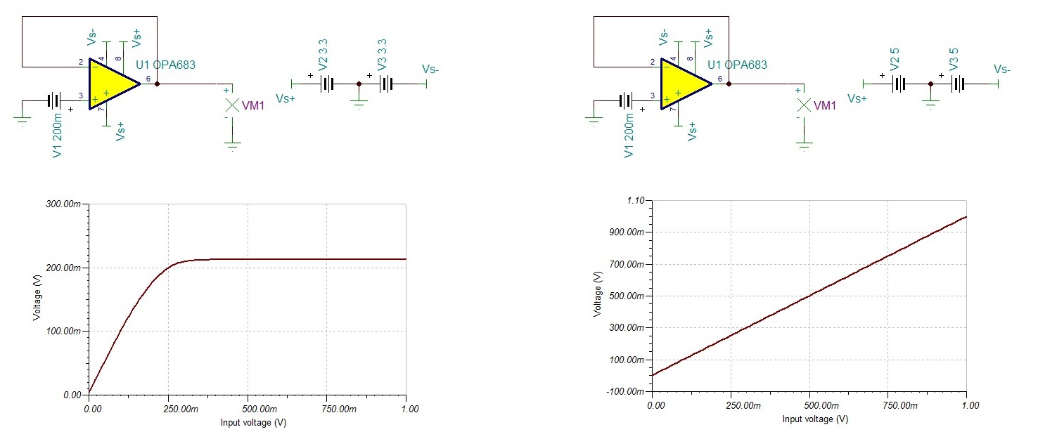
Hi, I have a simple op-amp voltage follower using OPA683. When the op-amp is powered by +3.3 V and -3.3 V supplies, the ouput voltage maxed out at ~200 mV when I change the input from 0 V to 1 V.
But when I change the power supply to +5 V and -5 V, the output follows the input.
Any idea why the 3.3 V circuit does not work as intended?
But when I change the power supply to +5 V and -5 V, the output follows the input.
Any idea why the 3.3 V circuit does not work as intended?