tinystorm
Newbie level 6
- Joined
- Feb 18, 2015
- Messages
- 14
- Helped
- 0
- Reputation
- 0
- Reaction score
- 0
- Trophy points
- 1
- Location
- A concrete cave
- Activity points
- 137
i was simulating this scenario. it is a current sense. 1A = 1v final ratio
as with many sense packages available commercially, they do state that there is linearity problems in the low mA ranges.
so i went to try out some stuff in the old multisim
the question is, by introducing a small negative rail (-1.2v), it seem to correct the op amp offset problem in the low mA sense (50-100mA)
im no expert in op amp, but am i on the right track? originally i simulated only with single supply. or is this just a multisim/simulation anomaly?
i have some actual op amps, but i could not plug those into 0.1" breadboards to try it w/o an adapter.
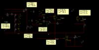
the neg rail in question comes from V3. the load supply comes from V2 --> probe 1, readout from probe8.
as with many sense packages available commercially, they do state that there is linearity problems in the low mA ranges.
so i went to try out some stuff in the old multisim
the question is, by introducing a small negative rail (-1.2v), it seem to correct the op amp offset problem in the low mA sense (50-100mA)
im no expert in op amp, but am i on the right track? originally i simulated only with single supply. or is this just a multisim/simulation anomaly?
i have some actual op amps, but i could not plug those into 0.1" breadboards to try it w/o an adapter.
the neg rail in question comes from V3. the load supply comes from V2 --> probe 1, readout from probe8.