Continue to Site

Welcome to EDAboard.com

Welcome to our site! EDAboard.com is an international Electronics Discussion Forum focused on EDA software, circuits, schematics, books, theory, papers, asic, pld, 8051, DSP, Network, RF, Analog Design, PCB, Service Manuals... and a whole lot more! To participate you need to register. Registration is free. Click here to register now.

Op Amp input impedance vs. attenuation

Status
Not open for further replies.

juz_ad

Full Member level 2
Full Member level 2
Joined
Dec 17, 2011
Messages
130
Helped
0
Reputation
0
Reaction score
0
Trophy points
1,296
Visit site
Activity points
2,541


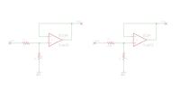
The config on the left has an an output that is approx. unity and an input Z of approx. 100K (set by R2).

The config on the right has an output that is attenuated by a factor of 100:1 - but (according to what I've been told...) also has an input Z of approx. 100K.

I understand the difference between the 2 R voltage dividers (1:100 and 100:1) - but how is the input Z the same for both configs?

Thanks.
 

A unity gain inverter has very high input impedance (because there is virtually no voltage across input terminals of opamp). You should think of many MOhms (of course depending on frequency of operation).

So your source is right, both circuits have same input impedance.
 

Status
Not open for further replies.

Similar threads

Part and Inventory Search

Welcome to EDABoard.com

Sponsor

Back
Top