Continue to Site

Welcome to EDAboard.com

Welcome to our site! EDAboard.com is an international Electronics Discussion Forum focused on EDA software, circuits, schematics, books, theory, papers, asic, pld, 8051, DSP, Network, RF, Analog Design, PCB, Service Manuals... and a whole lot more! To participate you need to register. Registration is free. Click here to register now.

One thing I cannot understand for op amp simulation

Status
Not open for further replies.

ownway

Newbie level 4
Newbie level 4
Joined
Nov 29, 2012
Messages
7
Helped
0
Reputation
0
Reaction score
0
Trophy points
1,281
Visit site
Activity points
1,352
I think it should be something elementary, however I really could not understand this:
I build up one example circuit just like below in Pspice 16(pls click to enlarge)

opamp.jpg

I know how op-amp works and how to calculate the gains. Normally I choose the R3=100k, R4=10k. In order to make my doubt more clear to you, I set R3=100, R4=10. And I choose a power op-amp LM675 instead of LM741. So the output gain is around 1+100/10=11. As you can see from the notation on the schematics, the input is 1V, and the output is 11V. So the simulation works.
But what I do not understand is that current goes in/out that op-amp. If you sum up the values of the current flowing through the 5 pins of LM675, the result is not 0! How could our simulation tool be against simple KCL? I don't understand. I know KCL will not work if you only take input and output pins into account(PIN1,2,4), but KCL should always work if you also consider the current from the voltage reference terminal(PIN3,5). Also as we already know, PIN4 as an output has a high voltage with high current, and this big current is supposed to be majorly contributed by the reference terminal PIN5. But the simulation shows that the current of PIN5 is much less than PIN4. You can also build up a circuit with different components in your own simulation tool, should be the similar result like me. Could anybody explain this to me? Thank you so much.
 

It could be that the 14.43mA is the typical supply current for this device at 20V and is disregarding the output current.
 

Either you have altered something and not allowed the simulator to re-calculate or the simulator package has a bug in it. Because you are correct the current out of pin 4 is the input current to pin 5 + a bit.
Frank

Thanks, I did not alter anything. Those component models come from the default package with Orcad Pspice. I also tried with some other models like LM741 and so on, they all have the similar results like this.
I used another computer here which has Multisim, same problem. It is really hard to believe that the major simulation tools have all failed to get such simple thing wrong.:???:

- - - Updated - - -

It could be that the 14.43mA is the typical supply current for this device at 20V and is disregarding the output current.

Maybe, but the output current should be considered. I don't understand why both of major simulation tools I tried seem to get such simple thing wrong. :s. That is why I started to doubt there is something I did not understand..
 

You can also build up a circuit with different components in your own simulation tool, should be the similar result like me. Could anybody explain this to me?
I just tried it with SIMetrix and got a similar result to you.
Apparently it's a common problem with simulators - they don't bother to calculate the current flowing through the V+ and V- pins properly.

I remember a thread about the same problem in the diyAudio forum. IIRC, some simulators get it right, but I forget which.

It is really hard to believe that the major simulation tools have all failed to get such simple thing wrong.:???:
Sad but true. :roll:
 

Are you sure it is not a problem with the model and the use of global node zero which doesn't appear on the pinout?

Keith
 

An animated simulation is especially helpful, to portray what happens when output is negative as well as when it is positive.

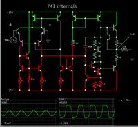
Below is a link to a simulation showing the internals of a 741 op amp. It is listed among the circuits at www.falstad.com/circuit. (Click Allow to load the Java applet.)

At the output, I added a resistive load whose other end goes to zero ground. You can watch current flow through the output terminal.

When output is positive, current comes into the device from the positive supply.

When output is negative, it draws current from ground through the load, into the output terminal, and down through the negative supply.

https://tinyurl.com/bl9geou

Screenshot:


Are you sure it is not a problem with the model and the use of global node zero which doesn't appear on the pinout?
Keith

Yes, I think we should not blame the simulator but instead the MODEL which is used to simulate opamp circuits.#As you probably know - it is a so called "macro model" that uses controlled sources and other "artificial" parts.
Therefore, it is no surprise that the KCL rules are not always fulfilled.
However, there are very few transistorized opamp models. I am pretty sure that all simulators will produce results which are in agreement with the KCL.

For example - such a model (741 type) is contained in LTSPICE .
 
Last edited:

Please correct me if i am wrong...

supply voltage = 20+20 =40V
supply current = 14.43+14.43= 28.86mA
supply power = 40v * 28.86mA = 1.1544w

output voltage = 11v
output current = 99.99mA
output power = 11v * 99.99mA =1.09989w

Loss = 1.1544-1.09989 = 0.05451w

the input voltage not equal to output voltage. So there may be variation in current...:roll:

Regards
Udhay
 

If you look at the macromodel for the LM675 you will see that the output current comes from egnd which is connected to nodes 99 and 0 and so does not takes its power from the supply pins.

It seems people are too quick to blame simulators for problems with models or bad designs. My experience of simulators is that they do what they are asked to do. If you give them dodgy models you will get dodgy results. If you simulate a bad circuit you will get bad results. I rarely find a true simulator bug.

Keith.
 
  • Like
Reactions: LvW

    LvW

    Points: 2
    Helpful Answer Positive Rating
I just tried it with SIMetrix and got a similar result to you.
Apparently it's a common problem with simulators - they don't bother to calculate the current flowing through the V+ and V- pins properly.

I remember a thread about the same problem in the diyAudio forum. IIRC, some simulators get it right, but I forget which.


Sad but true. :roll:

Thank you for giving an actual test. It is very helpful to know an outcome from another simulator by another person. :)

- - - Updated - - -

An animated simulation is especially helpful, to portray what happens when output is negative as well as when it is positive.

Below is a link to a simulation showing the internals of a 741 op amp. It is listed among the circuits at www.falstad.com/circuit. (Click Allow to load the Java applet.)

At the output, I added a resistive load whose other end goes to zero ground. You can watch current flow through the output terminal.

When output is positive, current comes into the device from the positive supply.

When output is negative, it draws current from ground through the load, into the output terminal, and down through the negative supply.

https://tinyurl.com/bl9geou

Screenshot:


Thanks for your contribution, it is a really good animation. And I think I understand the same way you stated. I also expect to see a bigger current from the supply terminal on my simulator, and I failed.
 

I just tried it with SIMetrix and got a similar result to you.
Apparently it's a common problem with simulators - they don't bother to calculate the current flowing through the V+ and V- pins properly.

I remember a thread about the same problem in the diyAudio forum. IIRC, some simulators get it right, but I forget which.


Sad but true. :roll:

Don't confuse model problems with simulator problems. The simulators are simulating exactly what has been defined by the models and schematic. The model is the problem.

Keith.
 

Yes, I think we should not blame the simulator but instead the MODEL which is used to simulate opamp circuits.#As you probably know - it is a so called "macro model" that uses controlled sources and other "artificial" parts.
Therefore, it is no surprise that the KCL rules are not always fulfilled.
However, there are very few transistorized opamp models. I am pretty sure that all simulators will produce results which are in agreement with the KCL.

For example - such a model (741 type) is contained in LTSPICE .

I think you get the point. It could be caused by a buggy model, I agree. I did not know too much about simulator. The model I used comes together with the simulator, so I thought they are supposed to be certified and "well-behaved". And I also expect the simulator to calculate or at least check the basic rules like KCL before portraying the result to the users.

Also FYI, I also tested with the "official" LM741 model in Pspice, it is not working.

- - - Updated - - -

Please correct me if i am wrong...

supply voltage = 20+20 =40V
supply current = 14.43+14.43= 28.86mA
supply power = 40v * 28.86mA = 1.1544w

output voltage = 11v
output current = 99.99mA
output power = 11v * 99.99mA =1.09989w

Loss = 1.1544-1.09989 = 0.05451w

the input voltage not equal to output voltage. So there may be variation in current...:roll:

Regards
Udhay

I think there is a mistake of calculating the power of the supply. You should either calculate this way: 20V*(14.43+14.43)mA or (20V*14.14mA)*2, the result is half of your calculation, e.g 0.5572w. The supply power is even less than the output power, that is why I think it is not realistic.
 
Last edited:

Yes, I think we should not blame the simulator but instead the MODEL...

It seems people are too quick to blame simulators for problems with models or bad designs. My experience of simulators is that they do what they are asked to do. If you give them dodgy models you will get dodgy results.
Agreed. Sorry if I gave the wrong impression earlier.

On a related note, SPICE models supplied by manufacturers for their transistors etc are often quite inaccurate as well. On the bright side, a collection of decent models for various BJTs, JFETs, MOSFETs, diodes etc, developed by Bob Cordell, is available on his website here.
 

If you look at the macromodel for the LM675 you will see that the output current comes from egnd which is connected to nodes 99 and 0 and so does not takes its power from the supply pins.

It seems people are too quick to blame simulators for problems with models or bad designs. My experience of simulators is that they do what they are asked to do. If you give them dodgy models you will get dodgy results. If you simulate a bad circuit you will get bad results. I rarely find a true simulator bug.

Keith.

Thanks for pointing that out, I did expect the simulator to exam the basic KCL rules even a bad model is used. At least an error about that model should be thrown out when such thing happens. Not to mention the models I used are embedded inside the tool :s
 

Thanks for pointing that out, I did expect the simulator to exam the basic KCL rules even a bad model is used. At least an error about that model should be thrown out when such thing happens. Not to mention the models I used are embedded inside the tool :s

The simulator can only work with the models and schematic it has. If someone creates a model with an internal voltage source connected to ground, what would you like the simulator to do? It solves the equations and produces the correct answer for the information it has been given. Even if you did probe the internal voltage source current it still wouldn't give the correct supply current because whoever created the model didn't try to make the supply current accurate.

The summation of ALL currents in the circuit will be correct. It is simply that you are not looking at them all. Look at the current in egnd to find out where the missing current is.

Models "embedded in the tool" are simply models included as part of the package and are usually supplied by device manufacturers, usually with a discalimer such as "Pspice Models are provided "AS IS, WITH NO WARRANTY OF ANY KIND" (National Semiconductor).

Keith.
 
  • Like
Reactions: LvW

    LvW

    Points: 2
    Helpful Answer Positive Rating
The simulator can only work with the models and schematic it has. If someone creates a model with an internal voltage source connected to ground, what would you like the simulator to do? It solves the equations and produces the correct answer for the information it has been given. Even if you did probe the internal voltage source current it still wouldn't give the correct supply current because whoever created the model didn't try to make the supply current accurate.

The summation of ALL currents in the circuit will be correct. It is simply that you are not looking at them all. Look at the current in egnd to find out where the missing current is.

Models "embedded in the tool" are simply models included as part of the package and are usually supplied by device manufacturers, usually with a discalimer such as "Pspice Models are provided "AS IS, WITH NO WARRANTY OF ANY KIND" (National Semiconductor).

Keith.

Thanks, Keith. Now I got your point finally. Sorry I didn't really understand the part when you talked about sourcing from egnd, now my puzzle is almost completely solved.
BTW, meanwhile I did another test with another simulator. I think with this simulator, it has a more realistic model inside, I build the same circuit and I got exact result I expected. Here is the image of the result:
opamp_NI.jpg
 

I am not sure whose model that is (I used the LM675 in my first check) but there is more than one model of the 741 around. I have one called LM741/NS supplied with SIMetrix and that models supply current reasonably well. Another one I have called LM741 (of unknown origin) doesn't model supply current properly. uA741 from TI doesn't do it properly and neither does UA741/301/TI from TI. Most models don't seem to bother trying to get it right so it is best not to rely on it.

Models are a constant source of problems (unlike the simulators which seem pretty robust). I was doing some SiGe:C design recently and the models wouldn't work at elevated temperatures. However, NXP fixed the model which is quite unusual - most manufacturers don't bother.

Just to add - the difference in the simulations is the model, not the simulator. If you try the same model in another simulator it will behave the same.

Keith.

Noted, thank you!
 

I just tried this in Proteus, it gives the same results as in your first post.
 

Status
Not open for further replies.

Similar threads

Part and Inventory Search

Welcome to EDABoard.com

Sponsor

Back
Top