Vermes
Advanced Member level 4

This inductance meter can be useful when you work with pulse power supplies. The simplest solution is based on connecting a coil of not known inductance with a capacitor of known inductance. Negative resistance should be given to created resonant circuit and then frequency of oscillation should be measured.
This design uses stabilizer 78L05 and FET BF256.
C1 = 3,74nF
C1a = 3,74nF
C2 = C1 + C1a
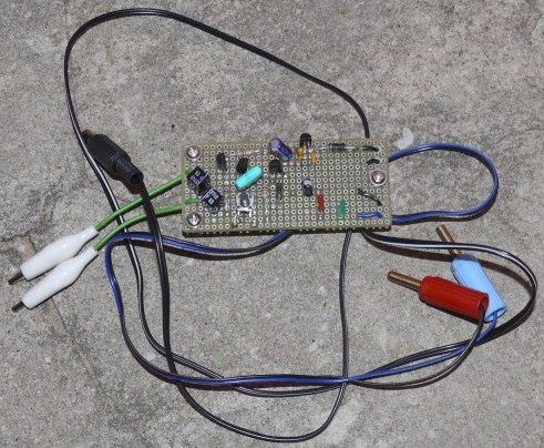
The system was mounted on a piece of universal board using a kynar. It was a test before creating a device with AVR and LCD display.
1% precise capacitors were used in this design. When the circuit was tested using 5% inductances, there was a surprise, because the circuit should look like that:

Instead of that, it was:

Large parasitic capacity Cx appeared in the circuit.
10uH inductance is triggered at 713 kHz – so Cx=1,2nF
22uH inductance is triggered at 460 kHz – so Cx=1,62nF
10uH inductance is triggered at 306 kHz – so Cx=1,99nF
That means that the parasitic capacity is not constant.
That is why the measurement of inductance is done by connecting two capacitors of known capacities.
This allows to calculate the value of parasitic capacitor:
And when you know that value, you can calculate the inductance:

The second capacitor and button were soldered to the PCB. The following measurements used 10% inductances:

Link to original thread - (Nie tak) prosty pomiar indukcyjności!