bhl777
Full Member level 6
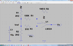
Hi everyone, I have a question about this circuit. I suppose C1 is used to remove DC of Vin, but how can we know the value of R3? It seems like we do not need R3 for calculating Vout/Vin, why it is there? Thank you!

Follow along with the video below to see how to install our site as a web app on your home screen.
Note: This feature may not be available in some browsers.

Apart from the points, that have been already explained, the shown circuit doesn't work correctly as a linear amplifier, because it misses a negative supply voltage respectively a suitable input bias.
The amplifier of the post #1 is absolutely wrong for LM107 though it is copied from the datasheet. The reason was already pointed out by FvM. V- shouldn't be tied to ground because the lowest amplitude of Vin needs to be higher than V- about 2V typically (in case of LM107).
It seems you tried in your amplifier of (post #5) creating a virtual ground so that you can use a single supply. It doesn't matter it is also wrong but since you thought about it I think you are ready to get the answer rather easily.
Usually (if not always), the bias of an opamp is set at its IN+. Its other input IN- will follow it automatically while the opamp output is not saturated. So let us assume we have a supply 0-5V and we like to set the virtual ground of an opamp as LM324 at 2.5V (actually I choose 1.8V since its output limit is 5-1.4=3.6V). As you did on your schematic we add a divider R+R and if necessary we bypass its mid node by a capacitor C. This node will be our virtual ground. For a few reasons, it is not recommeded to connect it directly to IN+.
To be continued...
Hello KerimF, could you tell me again which part of the diagram in #5 is wrong? Since I saw your answer now, I didn't find out where should I need to revise. Thank you for your advise!
It misses a feedback voltage divider. The negative OP inout is shorted to ground, AC-wise. As a result, the amplifier is operated with the OP open-loop gain, if C is suffcient large.which part of the diagram in #5 is wrong?