Continue to Site

Welcome to EDAboard.com

Welcome to our site! EDAboard.com is an international Electronics Discussion Forum focused on EDA software, circuits, schematics, books, theory, papers, asic, pld, 8051, DSP, Network, RF, Analog Design, PCB, Service Manuals... and a whole lot more! To participate you need to register. Registration is free. Click here to register now.

Non-ideal inverting amplifier gain is different depending on how to solve it. Why?

Status
Not open for further replies.

CHL

Member level 3
Joined
Jan 20, 2015
Messages
60
Helped
2
Reputation
4
Reaction score
2
Trophy points
8
Activity points
550
Untitled.png

Hi

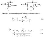
When I tried to analyze an inverting amplifier gain, there was a problem

As you can see above, eq(12.2) is from Figure 12.1 [Razavi, Design of Analog CMOS IC]

However, if the gain is derived by using feedback technique, the equation is 12.4.

They have Rout/R2, but one is at denominator and the other is at numerator.

Can you explain why they show a difference?

I think the equations should be same although there is a finite Rout.

Thanks
 

Does your book show any of the details of how they derived Eq. 12.3?

If you can post them that will help us to determine where the difference in the two expressions came from.
 

I agree with you.
It is not clear how Eq. (12.4) was derived.
The book simply states:.... using feedback techniques as described in chapter 8.....
So the reader is invited to read chapter 8 - hoping that he will find the corresponding part.
More than that, this sentence sounds a bit confusing because Eq. (12.2) is also, of course, the result of feedback.
My recommendation: Do not spend too much time for clarification.
It is not very important.
 

Status
Not open for further replies.

Part and Inventory Search

Welcome to EDABoard.com

Sponsor

Back
Top