Continue to Site

Welcome to EDAboard.com

Welcome to our site! EDAboard.com is an international Electronics Discussion Forum focused on EDA software, circuits, schematics, books, theory, papers, asic, pld, 8051, DSP, Network, RF, Analog Design, PCB, Service Manuals... and a whole lot more! To participate you need to register. Registration is free. Click here to register now.

Noise in AC Ceiling Fan speed control using TRIAC

Status
Not open for further replies.

shanmugapriyap

Newbie level 3
Joined
Mar 31, 2017
Messages
3
Helped
0
Reputation
0
Reaction score
0
Trophy points
1
Activity points
26
Hi

I tried to control the speed of Ceiling fan using triac. The speed was controlled but I got a noise in fan at all speeds.

I tried in many ways but no improvement in noise reduction.

Are there any alternative methods for TRIAC speed control with zero noise.

I have used PIC16F877A for speed control using triac.
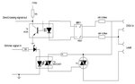
I have attached the code and circuit dagram that i have tried for your reference.

Code:
void interrupt ISR()
{
    if (INTCONbits.INTF)
    {
        ZC = 1; //zc RB0(external interrupt) pin
        INTCONbits.INTF = 0;
    }
}

void main() 
{
    long temp=0;
    TRISB = 0x01;                            //RB0 input for interrupt
    TRISD = 0;                                 //PORTD all output
    OPTION_REGbits.INTEDG = 0;     //interrupt  falling edge
    INTCONbits.INTF = 0;                 //clear interrupt flag
    INTCONbits.INTE = 1;                 //enable extrn interrupt 
    INTCONbits.GIE = 1;                  //enable global interrupt
    while (1)
    {

        if(temp>=40000)
        {
           temp=0;
           dimming=dimming+50;
           if(dimming>=120)
           {
                dimming=0;         
           } 
        }
        temp++;
        
        if (ZC)
        { 
            delay(dimming); 
            PORTDbits.RD0 = 1;    //Send a pulse
            __delay_us(250);
            PORTDbits.RD0 = 0;
            ZC = 0;
        }
    }
}


void delay(int maal)
{
    for (x=1; x< maal; x++)
    {
    __delay_us(50); // 65 for 60Hz
    }
}
 

Attachments

  • triac control.jpg
    triac control.jpg
    34 KB · Views: 244

It's not clear what you tried, neither if the presented circuit achieves a clean phase angle control. We would need to see oscilloscope waveforms to know clearly.

There are many previous threads about triac fan control, also some discussing noise. It's usually stated that a LC filter is required to reduce the noise, also that MOC3021 with inductive load (e.g. fan motor) requires a RC snubber for correct operation.

Effective alternatives to triac phase angle control like high frequent IGBT chopper are probably beyond the scope of your project. Switched series resistors can be a cheap option, but are dissipating heat.
 

Post the exact circuit and latest .hex file. I will simulate the circuit and see if there is any problem.
 

What is the logic behind that ?

Code:
           dimming=dimming+50;
           if(dimming>=120)
           {
                dimming=0;         
           }

It seems like the phase is continuously changing in big steps.
 

Post the exact circuit and latest .hex file. I will simulate the circuit and see if there is any problem.

already posted circuit only i used with snubber

triac.png

also attached the hex file

- - - Updated - - -

What is the logic behind that ?

Code:
           dimming=dimming+50;
           if(dimming>=120)
           {
                dimming=0;         
           }

It seems like the phase is continuously changing in big steps.


Here dimming is a delay.
At the detection of zero crossing triac is off for some time.
By varying the triac off time the fan speed is controlled.
Simply i gradually increase the fan speed like 50,100,120...
 

Attachments

  • pic_tric1.X.production.rar
    400 bytes · Views: 116

What is the frequency of Crystal you are using ? Does your XC8 code have

Code:
#define _XTAL_FREQ XXXXXXXXX
where XXXXXXXXX is your Crystal frequency as the first line ?

Why not use the XC8's

Code:
__delay_ms()
function to get the delays ?


Anyways, you have to use Timer Interrupts otherwise it will not work fine. You will need a potentiometer or button to change the firing angle and if you use a button then it will have a 50ms debounce delay and this will make Triac fire erratically.
 
Last edited:

I am interested in helping you with a .hex file to check if your fan really makes noise or not with a proper dimmer code but I can't help with code. Here I am attaching the .hex file I made for you to test on hardware. I have used the same connections as yours but have added one button to RC0 pin. See the PDF in the attached file for button connection. I have used 24V in proteus because using 230V AC in Proteus was not simulating the Triac. Don't follow my component values. Only follow my button circuit and test the attached .hex file. I have used 4 MHz Crystal (not shown in my Schematic). Also see the Proteus Simulation Video in the attachment.

If it works fine without noise then give me the real world data that is what output powers you need and I will change the triac firing steps accordingly to get the required output powers and post new .hex file. if you are going to make product and sell it then better use PIC12F device.
 

Attachments

  • Dimmer.rar
    375.6 KB · Views: 120
Last edited:

The noise is caused by wave form distortion due to conduction of Thyristor. The noise will be low if thyristor is triggered near voltage zero crossing, thus passing nearly entire half cycles of a.c. to load. For resistive load, there will be no noise.
 

You shuld flag zero crossing variable ZC at each transition, but with your logic it is likely allowing trigger any time during positive cycle of the wave. The circuit you are using seems more like a simple rectifier, which is not able to generate a narrrow pulse.
 

I don't have a solution but I heard about this kind of humming sound coming from motors driven by non sineshape waveforms. It was a chief reason I purchased a sinewave inverter for my backup power system, and not a square-wave or modified sinewave type.
 

Code:
You shuld flag zero crossing variable ZC at each transition, but with your logic it is likely allowing trigger any time during positive cycle of the wave

In the given circuit, zero cross pulse is generated at each transition. Once this zero cross pulse, used as external interrupt source, is detected, the ZC flag is set. So I cannot get the point raised at #9.
 

In the given circuit, zero cross pulse is generated at each transition. Once this zero cross pulse, used as external interrupt source, is detected, the ZC flag is set. So I cannot get the point raised at #9.

You're correct, I did not pay enough attention to the above interruption routine. I recall the comments placed on post 2 as the most probable reasons, which where confirmed at least in part at post 6.
 

Status
Not open for further replies.

Similar threads

Part and Inventory Search

Welcome to EDABoard.com

Sponsor

Back
Top