Continue to Site

Welcome to EDAboard.com

Welcome to our site! EDAboard.com is an international Electronics Discussion Forum focused on EDA software, circuits, schematics, books, theory, papers, asic, pld, 8051, DSP, Network, RF, Analog Design, PCB, Service Manuals... and a whole lot more! To participate you need to register. Registration is free. Click here to register now.

[SOLVED] Nodal Analysis Currents Direction

Status
Not open for further replies.

tahir4awan

Full Member level 4
Joined
Nov 29, 2010
Messages
208
Helped
16
Reputation
32
Reaction score
17
Trophy points
1,308
Location
Germany
Activity points
3,084
I always hate nodal analysis because it is your headache to point currents directions unlike mesh analysis.
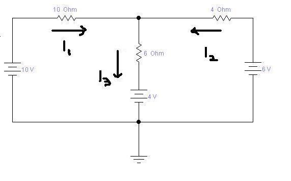
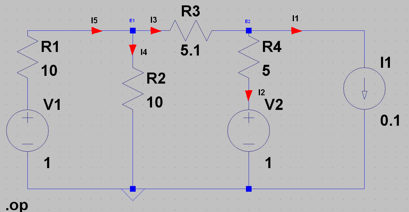
I attached a simple circuit can you guys what will be current equation for this circuit?


It is very simply,
I1 + I3 + I2 = 0

(10V - Va)/10Ω + (4V - Va)/6Ω + (6V - Va)/4Ω = 0

And if we solve this we get

Va*(1/10Ω + 1/6Ω + 1/4Ω) = 10V/10Ω + 4V/6Ω + 6V/4Ω

Va*31/60 = 19/6

Va = (19/6) / (31/60) = 19/6 * 60/31 = 190/31

Va = 190/31 = 6.12903226V

Node voltage method : DC NETWORK ANALYSIS
 
Last edited:
Thank you very much but there is a confusion Kirchoff's current law says that current(s) entering into a node equal current(s) leaving the node.
In this circuit all currents are pointed towards same node but no current is leaving the node............
 

No confusion. Current entering the node is I1+I2+I3. Current leaving is zero. So I1+I2+I3=0.

The current directions are not drawn correctly but that doesn't matter because one or more will be negative when you solve the equations.

Keith
 

Here you have two more examples:

First


For this circuit from KCL

I3 = I1 + I2

(Va - 4V)/6Ω = (10V - Va)/10Ω + (6V - Va)/4Ω

And after solve this I get

Va -> 190/31 = 6.12903226V


Second


And again form KCL

(-I1) + (-I2) + (-I3) = 0

Or

- I1 - I2 - I3 = 0

So know all current flow outward (away) from the node.
So this assume that voltage at node Va should be at higher potential.
And current flow from + to - , I assume that if current entering into a node I give him " +"
and current that come out form the node I give "-".
But you can choose whatever you wont but you must be consistent in your choice

So I can write:

-(Va - 10V)/10Ω - (Va - 6V)/4Ω - (Va - 4V)/6Ω = 0

And again the answer is exactly the same

Va -> 190/31 = 6.12903226V

And maybe another example for this diagram I choose


So I can write

I5 = I4 + I3
I1 = I3 - I2

(V1 - E1)/R1 = E1/R2 + (E1 - E2)/R3 (1)

I1 = (E1 - E2)/R3 - (E2 - V2)/R4 (2)

And after solving I get
E1=0.5V and E2=0.5V


But I can choose that all current flow out from the node
Then

-(E1 - V1)/R1 - E1/R2 - (E1-E2)/R3 = 0

-(E2 -E1)/R3 - (E2 - V2)/R4 - I1 = 0

And again after solve this I get the same result.
 
Last edited:
Hi all
KCL is very simple , the sum of currents entering and leaving a node is equal to zero , so when you denote the currents direction you must keep in there is at least one current is going out of node ,and at least one current leaving it , and then you denote the signs negative for leaving and positive for leaving or vice-verse . and continue your work
 

so when you denote the currents direction you must keep in there is at least one current is going out of node ,and at least one current leaving it

Not true. As the first example all currents can be drawn going into the node. The solution of the equations will result in at least one current being negative, denoting the current is in the opposite direction to that drawn.

Keith.
 

hi keith
i meant if he took all the currents going out , he must at least make one of them going in
 

As I said, it really doesn't matter. Direction will come from solving the equations. It is possible that all currents are zero.

Keith.
 

Keith, I suppose you mean the sum of all currents, don't you?
 

What I meant was that a particular problem could have the solution where i1=0, i2=0 and i3=0 so there is no "direction". You cannot always guess the direction correctly until you have solved it.

Keith.
 

I got a mothd more simple.
It is the Meshes current method;
(10+6)*I1 + 6*I2 =10-4;
6*I1 + (4+6)*I2 =6-4;
I1 + I2 + I3 =0.
the equations look like a matrix so it can use a copmuter to calculate it and the answer is :
I1 = 12/31A;
I2 = -1/31A;
I3 = -11/31A.
 

You are right xjf20072608 that mesh analysis is very simple. I personally prefer mesh method but when your teacher says solve the circuit using node analysis then problem arise.
 

The direction you draw doesn't matter. If you draw it the wrong way you will get a negative result. If you draw it the right way you will get a positive result.

Keith.
 
Status
Not open for further replies.

Similar threads

Part and Inventory Search

Welcome to EDABoard.com

Sponsor

Back
Top