Glant
Newbie level 3

- Joined
- Nov 16, 2014
- Messages
- 3
- Helped
- 0
- Reputation
- 0
- Reaction score
- 0
- Trophy points
- 1
- Location
- Massachusetts
- Activity points
- 25
No current copied from the current mirror to the amplifier
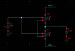
Hi, I'm designing an amplifier using a current produce a tail current, however, the current is not successfully copied to the amplifier, I think there is something wrong with the differential input signal on the upper left, can someone take a look at my circuit and give some advice, please?
Thanks very much.
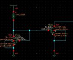
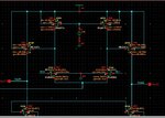
Here are the schematic of the circuit:


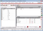
The last picture is the parameters of this circuit, Vdiff_DC is the differential input signal, Vin is the amplitude of V2, ln1 is the channel width of NM1 and NM0, ln2 is the width of NM2 and NM3, ln3 is the width of NM4 and NM5, lp1 is the width of PM1 and PM0, lp2 is the width of PM2 and PM3.
I don't think there are problems with W/L of these transistors so I don't give all the information about them, Vdc2 is the voltage source connected with the gate of PM0 and PM1, and Idc is the current source on the lower left.
You can see the the drain current of NM4 is not the same with the one in NM5, and I really don't know what the matter is.
Please take a look for me, thanks very much!
Hi, I'm designing an amplifier using a current produce a tail current, however, the current is not successfully copied to the amplifier, I think there is something wrong with the differential input signal on the upper left, can someone take a look at my circuit and give some advice, please?
Thanks very much.
Here are the schematic of the circuit:


The last picture is the parameters of this circuit, Vdiff_DC is the differential input signal, Vin is the amplitude of V2, ln1 is the channel width of NM1 and NM0, ln2 is the width of NM2 and NM3, ln3 is the width of NM4 and NM5, lp1 is the width of PM1 and PM0, lp2 is the width of PM2 and PM3.
I don't think there are problems with W/L of these transistors so I don't give all the information about them, Vdc2 is the voltage source connected with the gate of PM0 and PM1, and Idc is the current source on the lower left.
You can see the the drain current of NM4 is not the same with the one in NM5, and I really don't know what the matter is.
Please take a look for me, thanks very much!
Last edited:
