Vermes
Advanced Member level 4
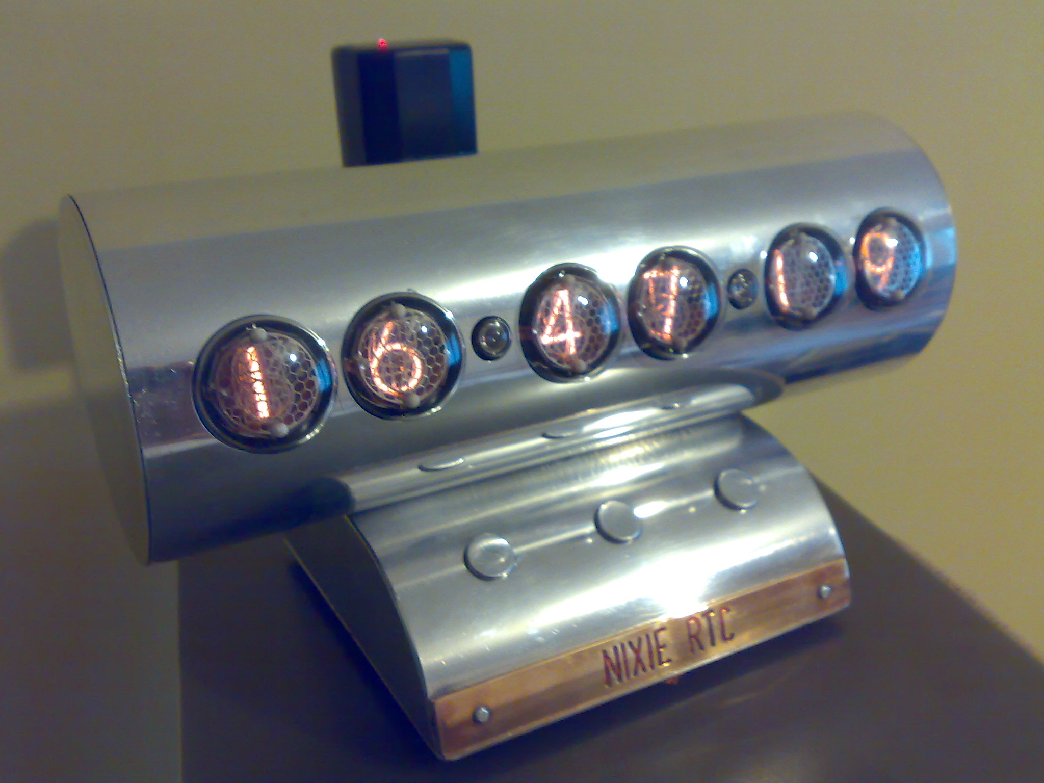
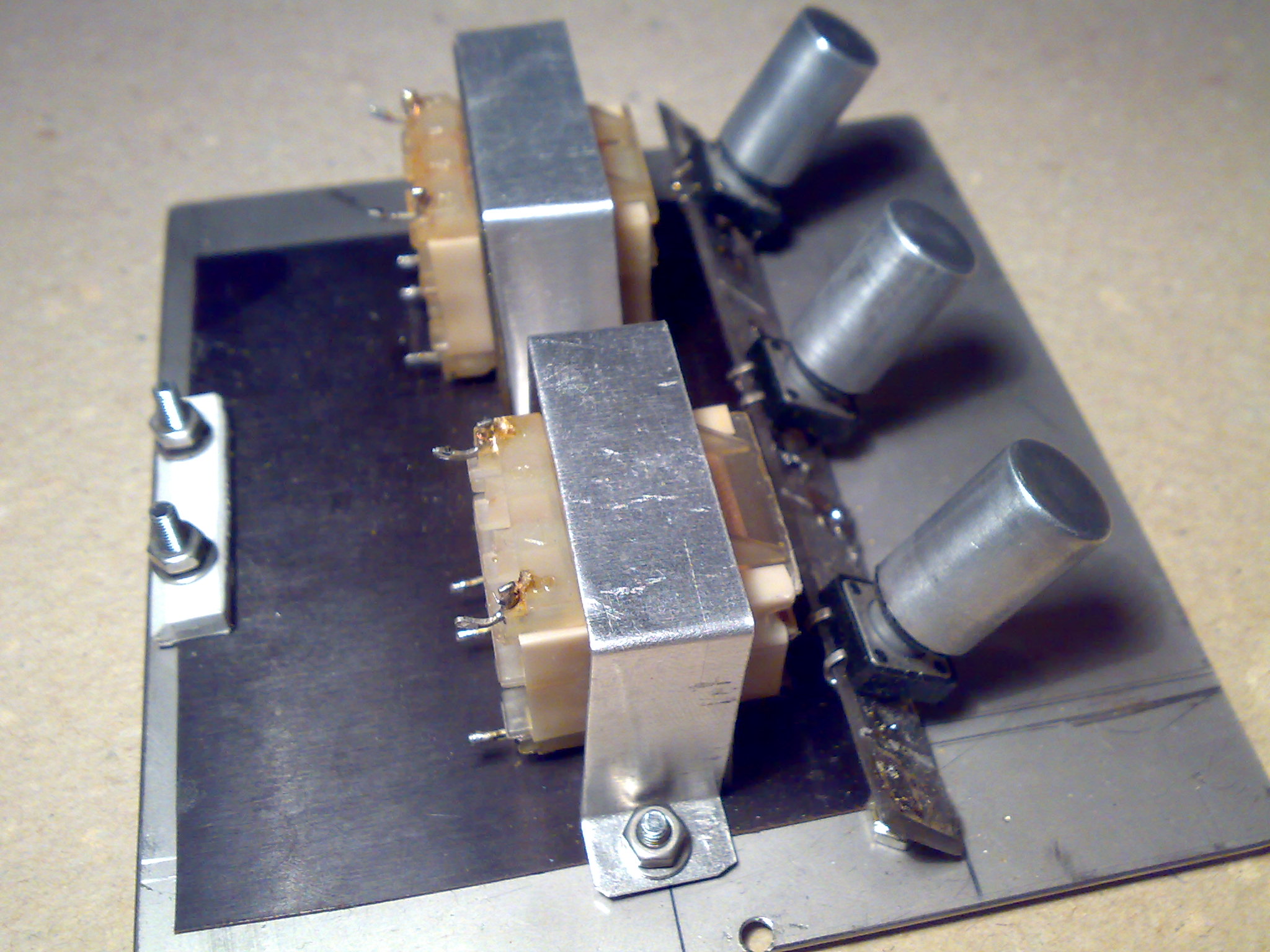
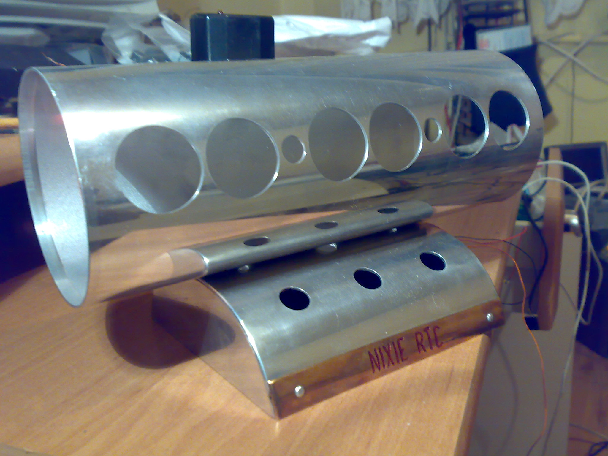
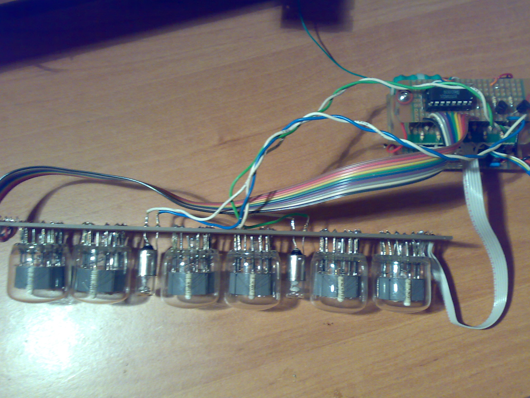
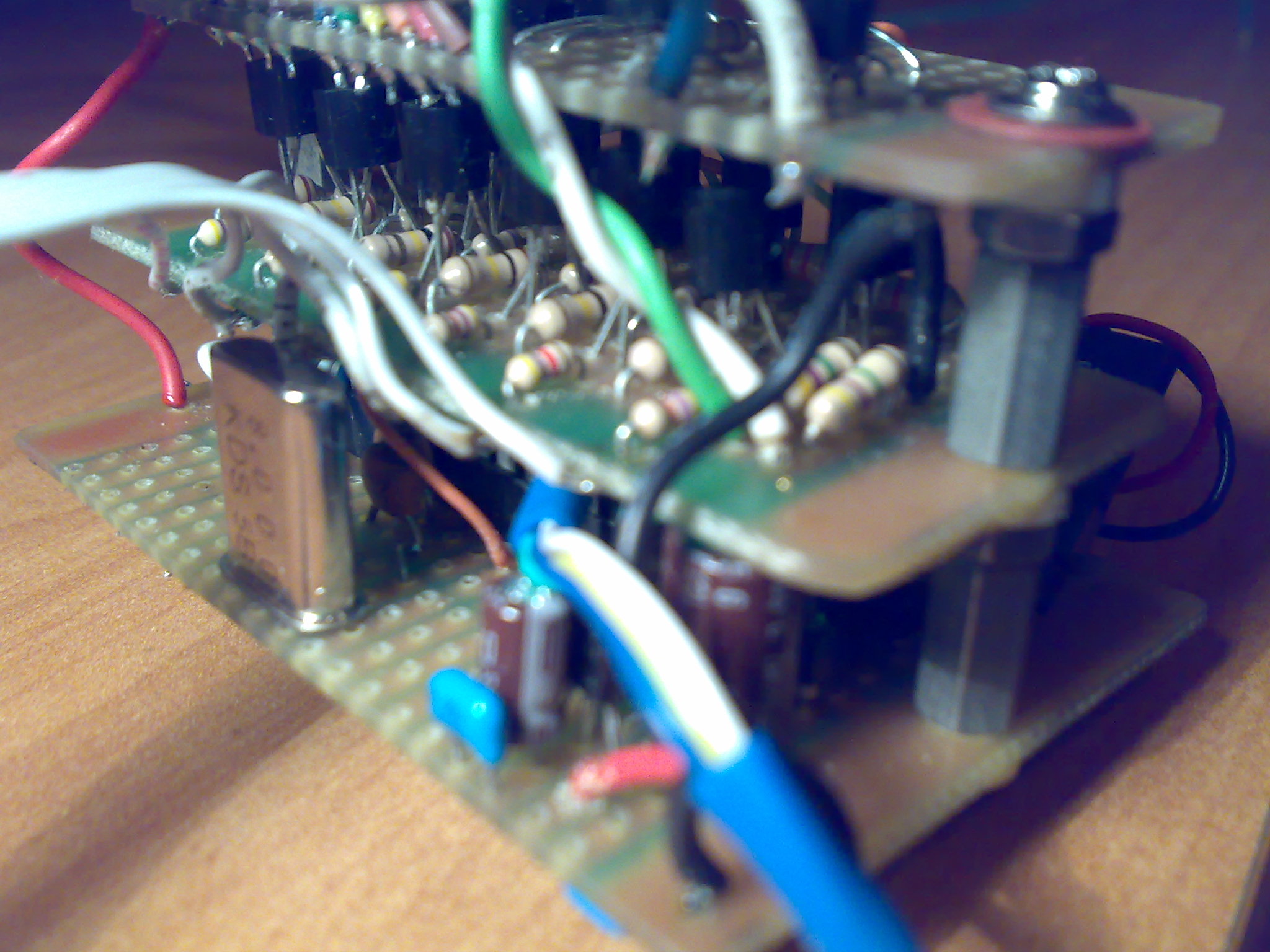
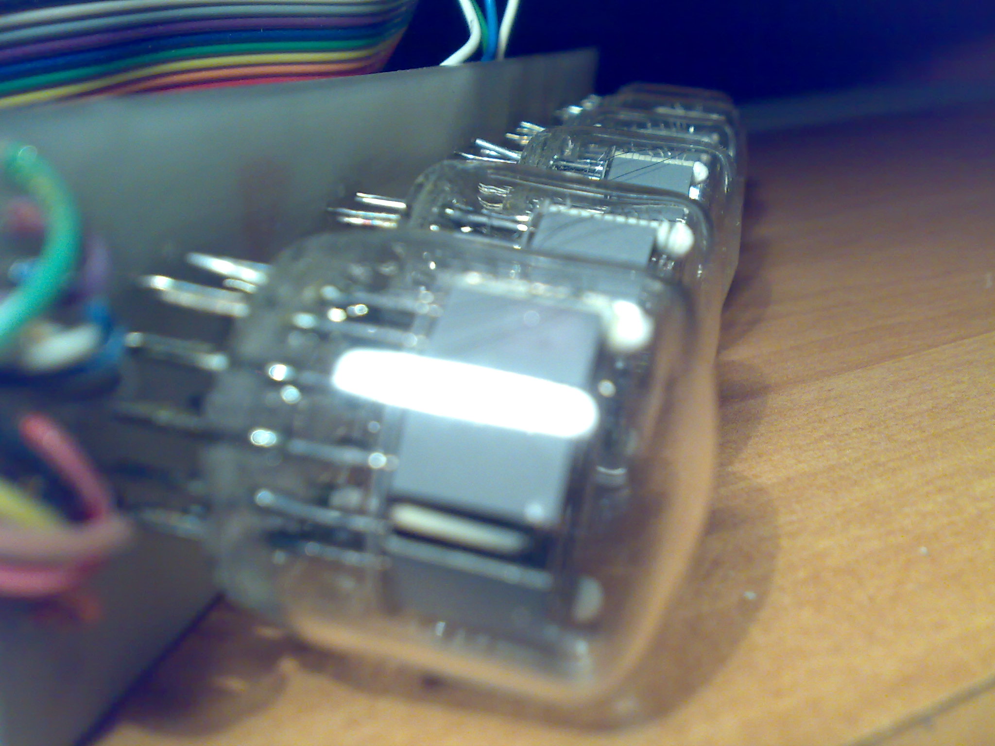
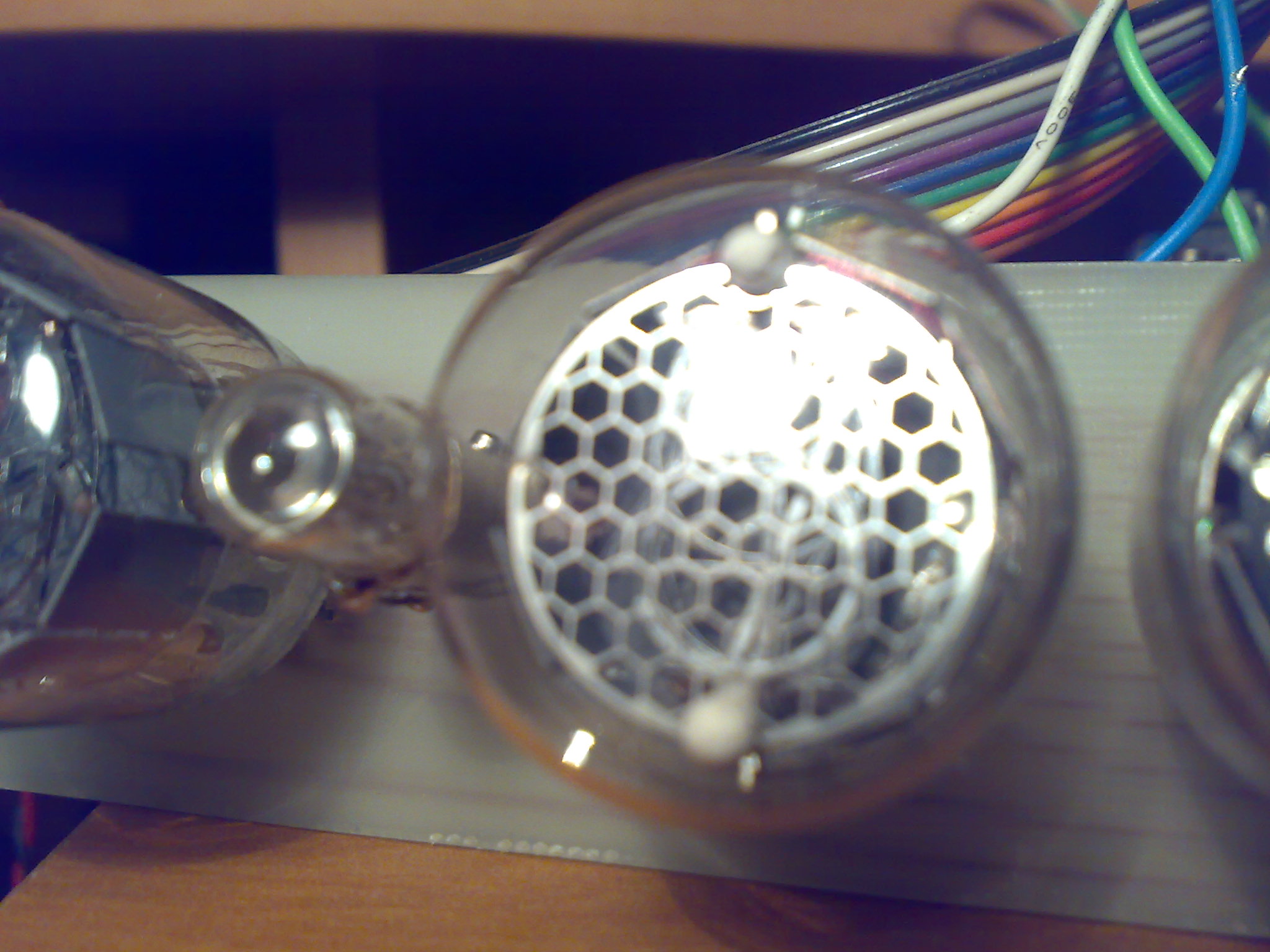
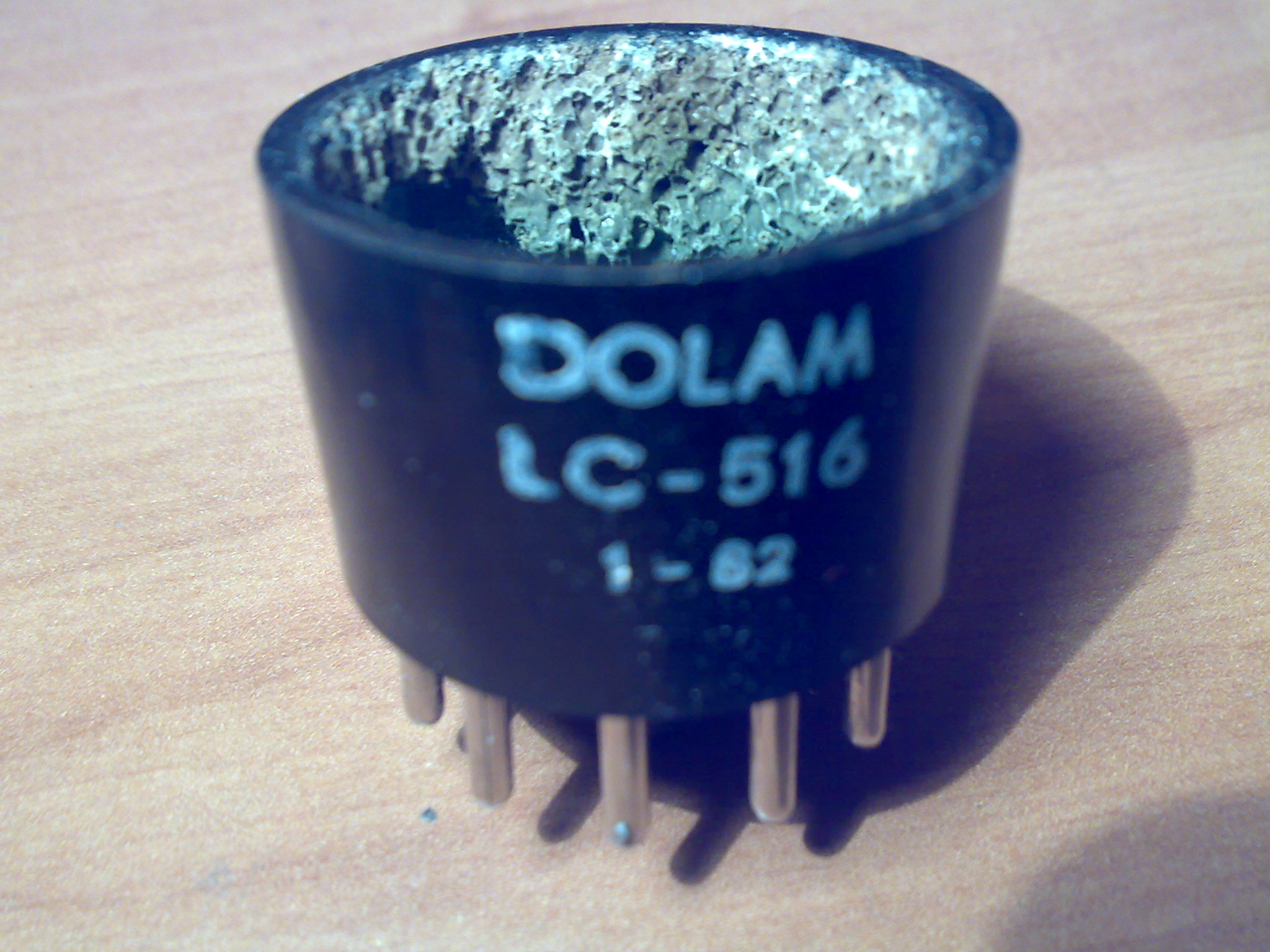
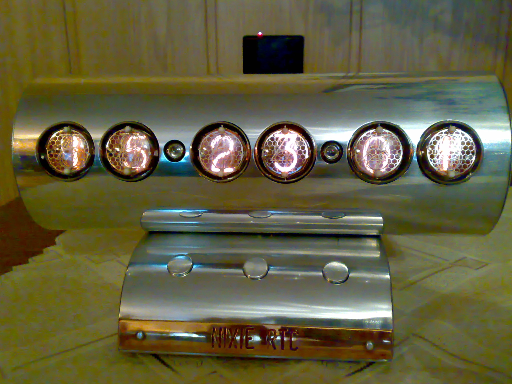
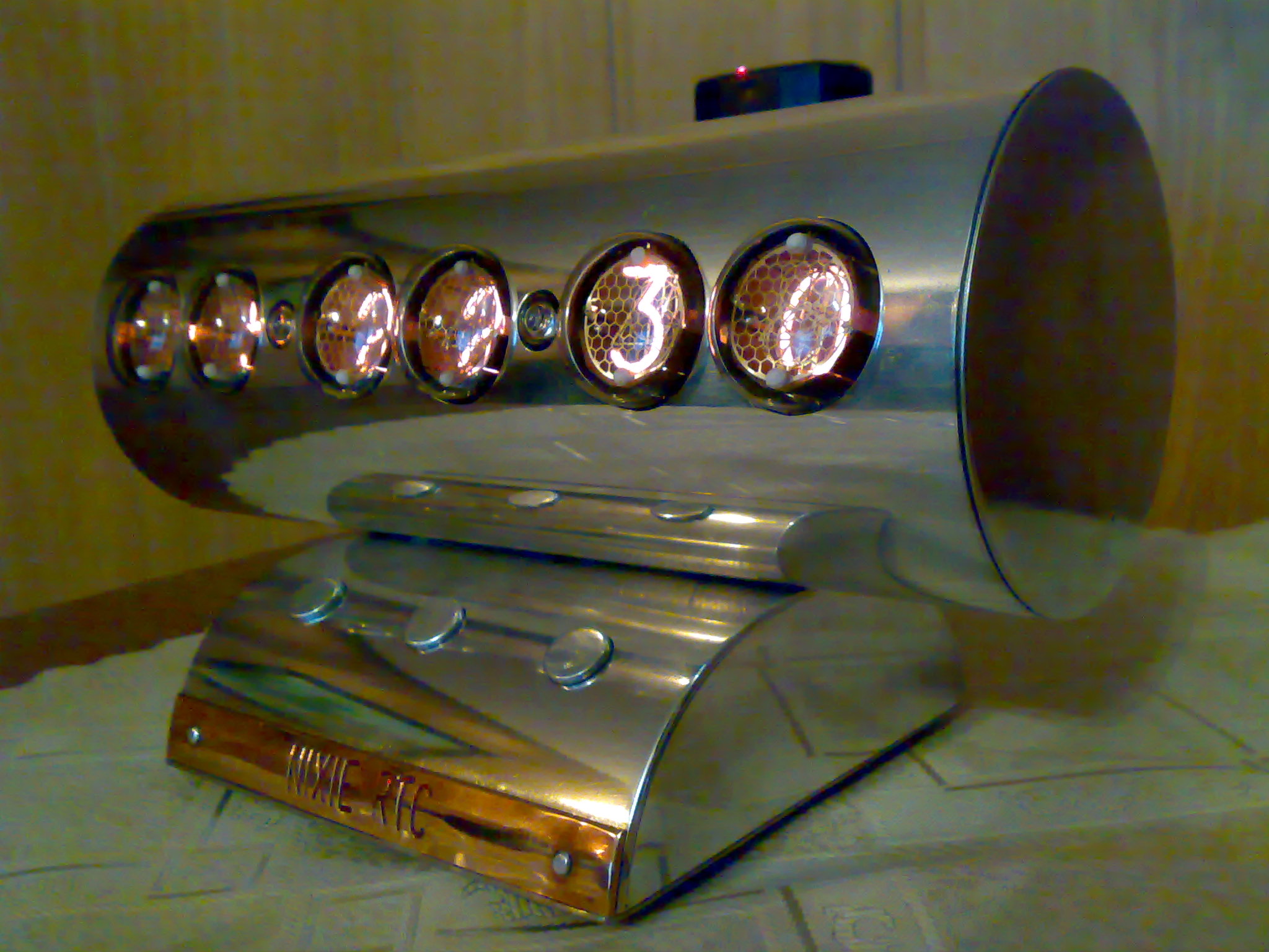
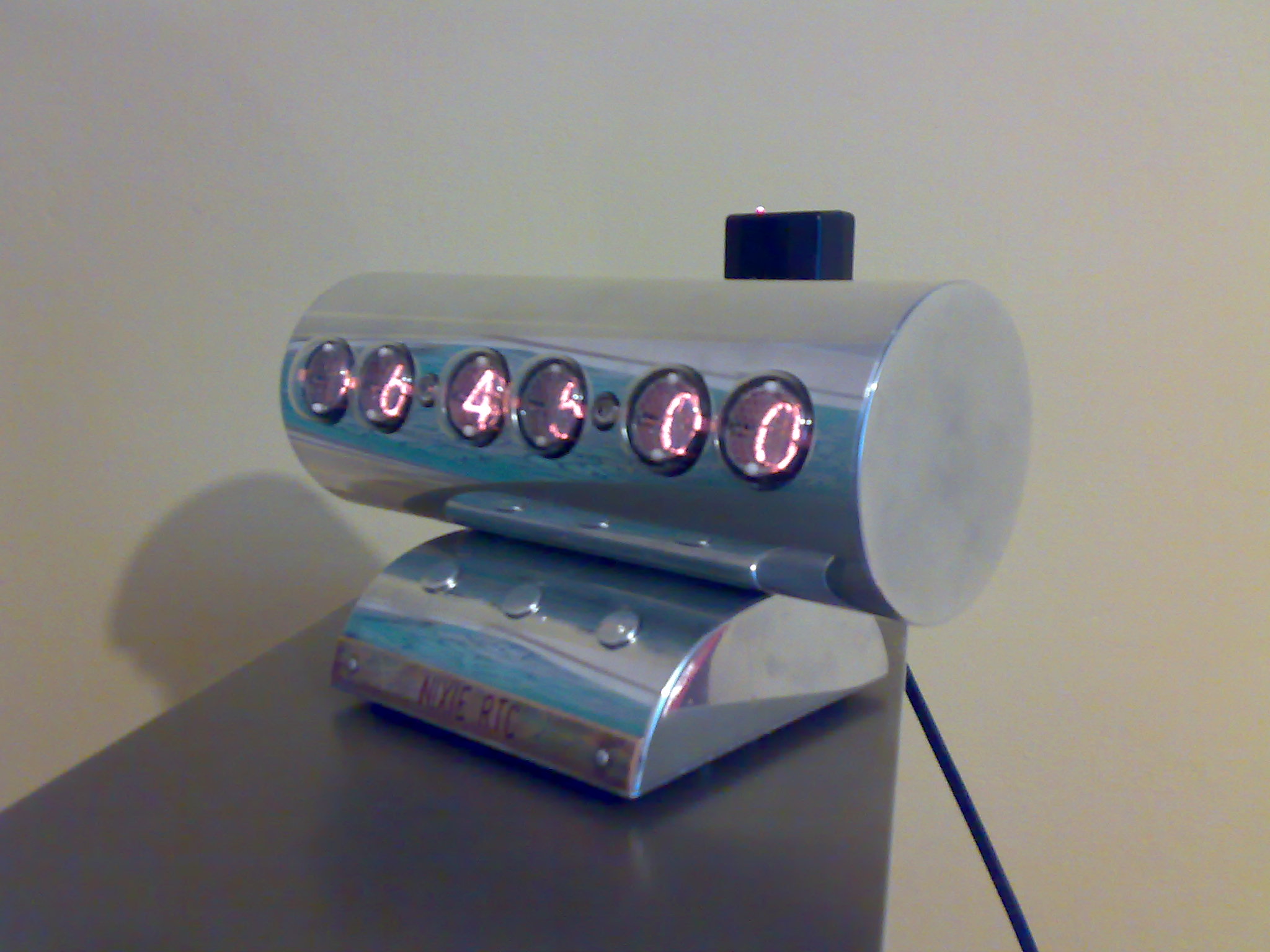
The clock was based on indicators LC-516. Aluminum housing (thin-walled tube from an old photocopier) and sanded. The indicators board is digested in an usual way and the rest was made on universal boards.
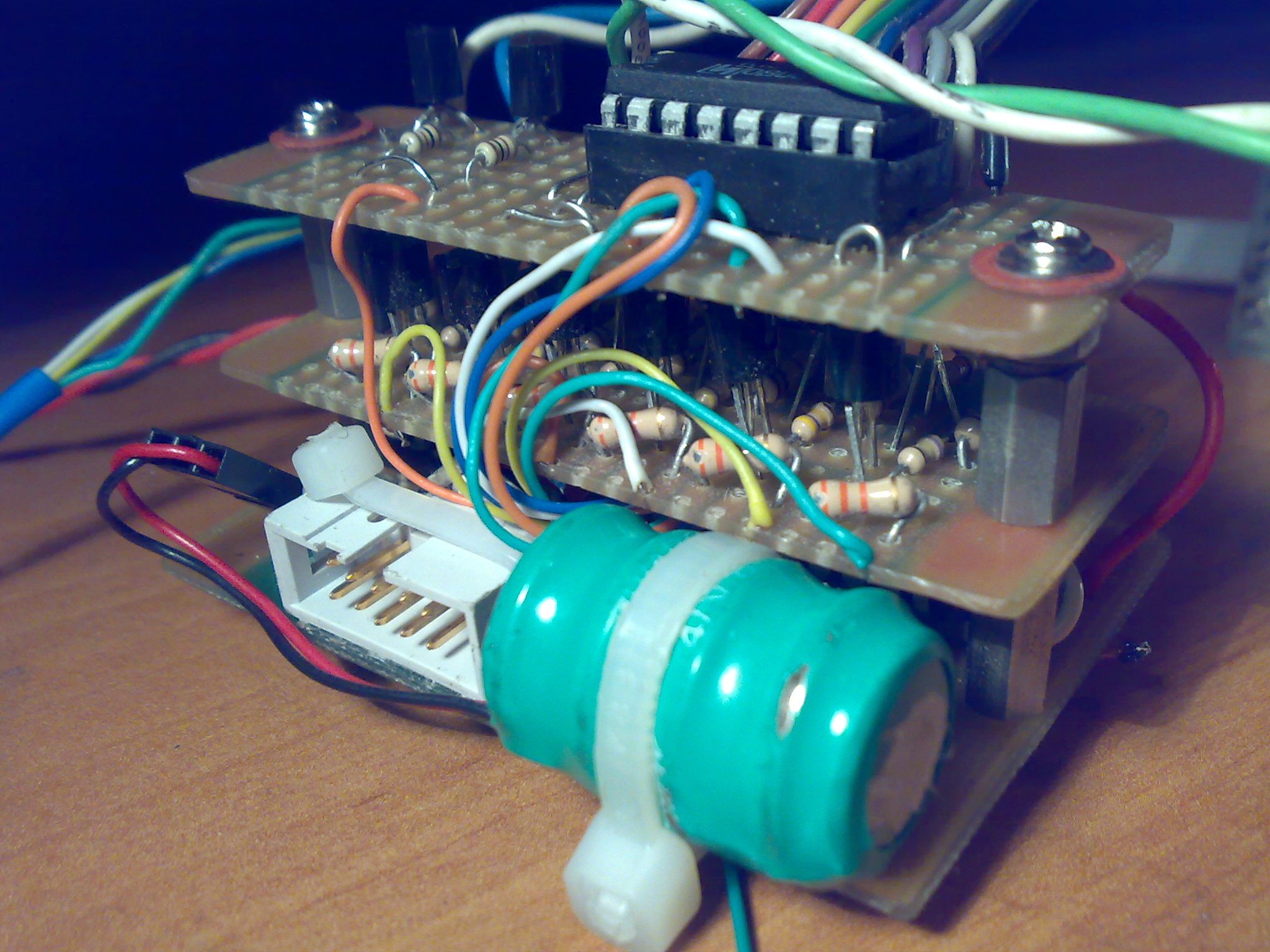
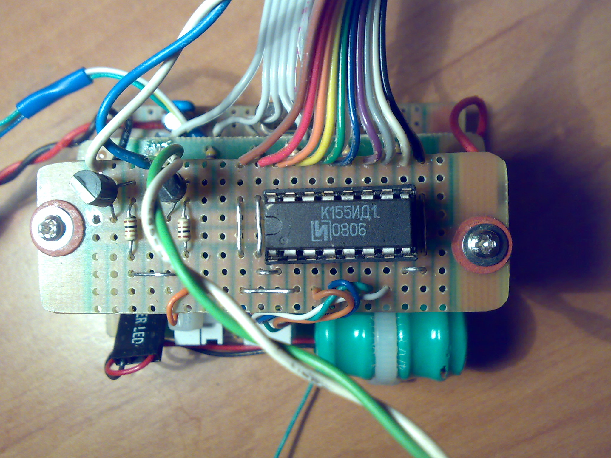
Tubes are multiplexed. From the side of anodes there are transistors MPSA42,92, and from the side of cathodes there is a decoder 74141 (its Russian equivalent K155ID1).
The main element of the clock is system rtc PCF8583, from which time and date is read. In the case of properly received frame by the DCF receiver, time in PCF is actualized. Additionally, system RTC is powered from 4,7V accumulator so the clock does not reset after power failure. The clock is equipped with a simple alarm and displays date after pressing one of the buttons. Full hour is indicated by a short beep.
The system uses microcontroller Atmega8.
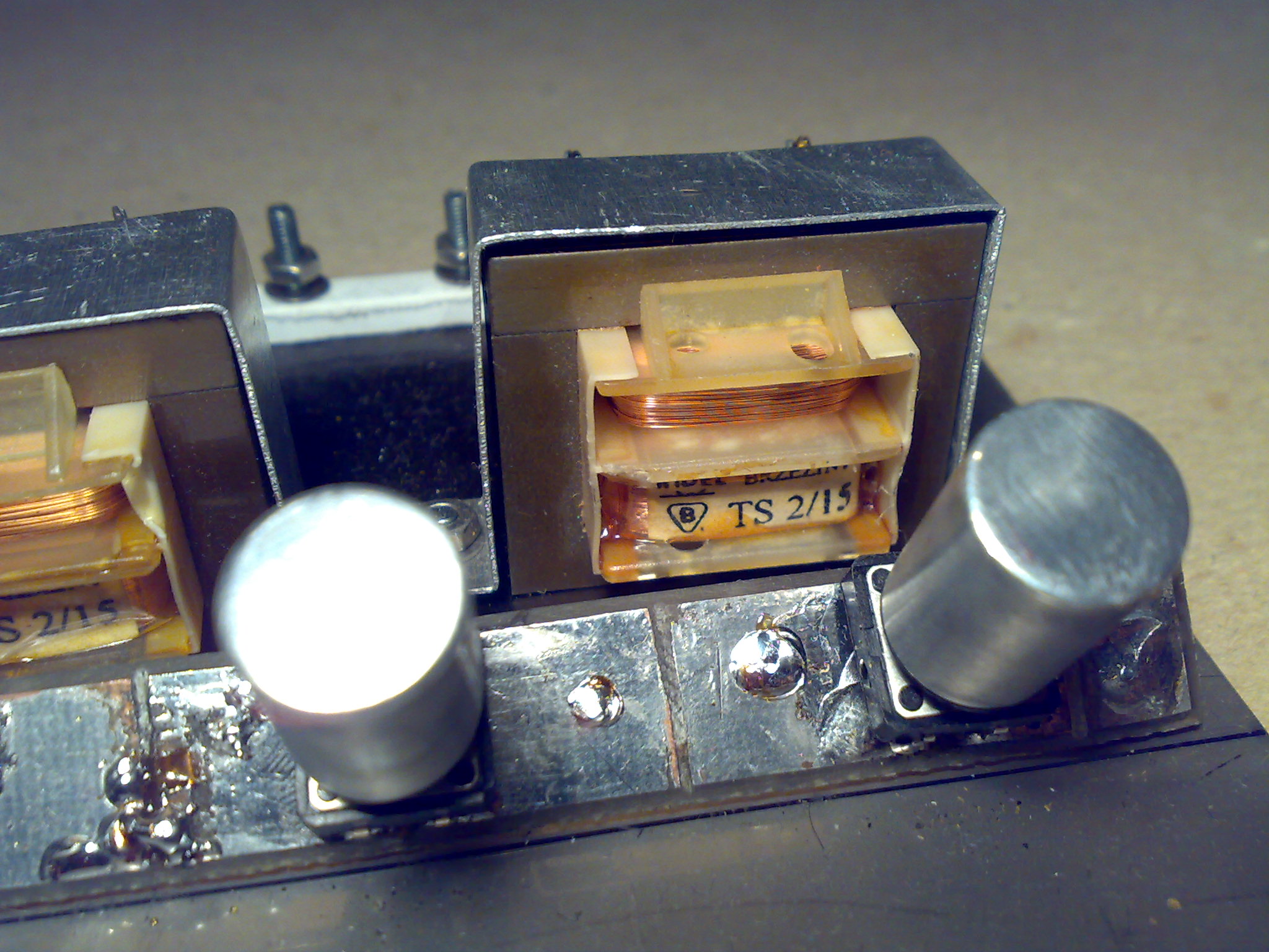
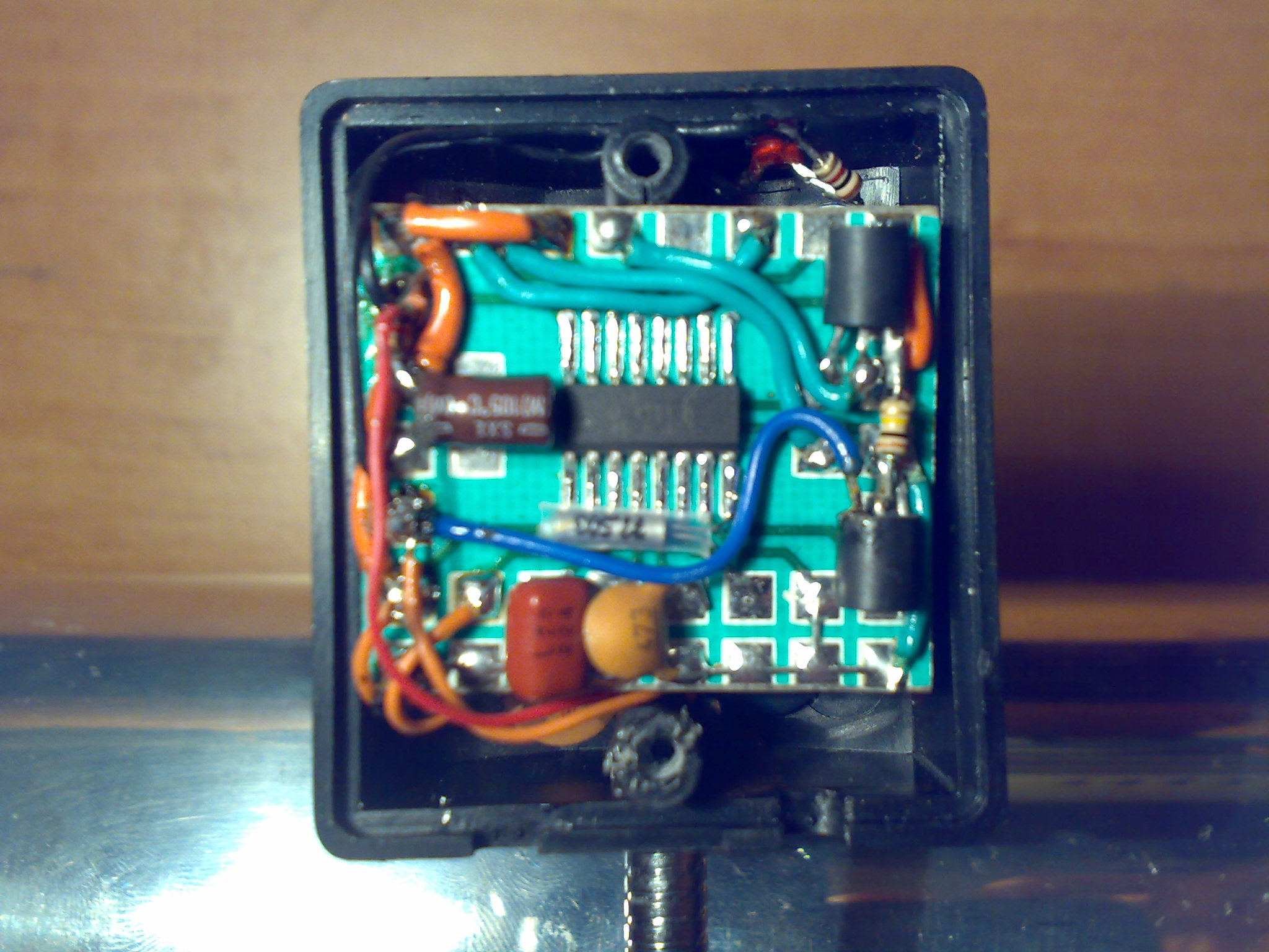
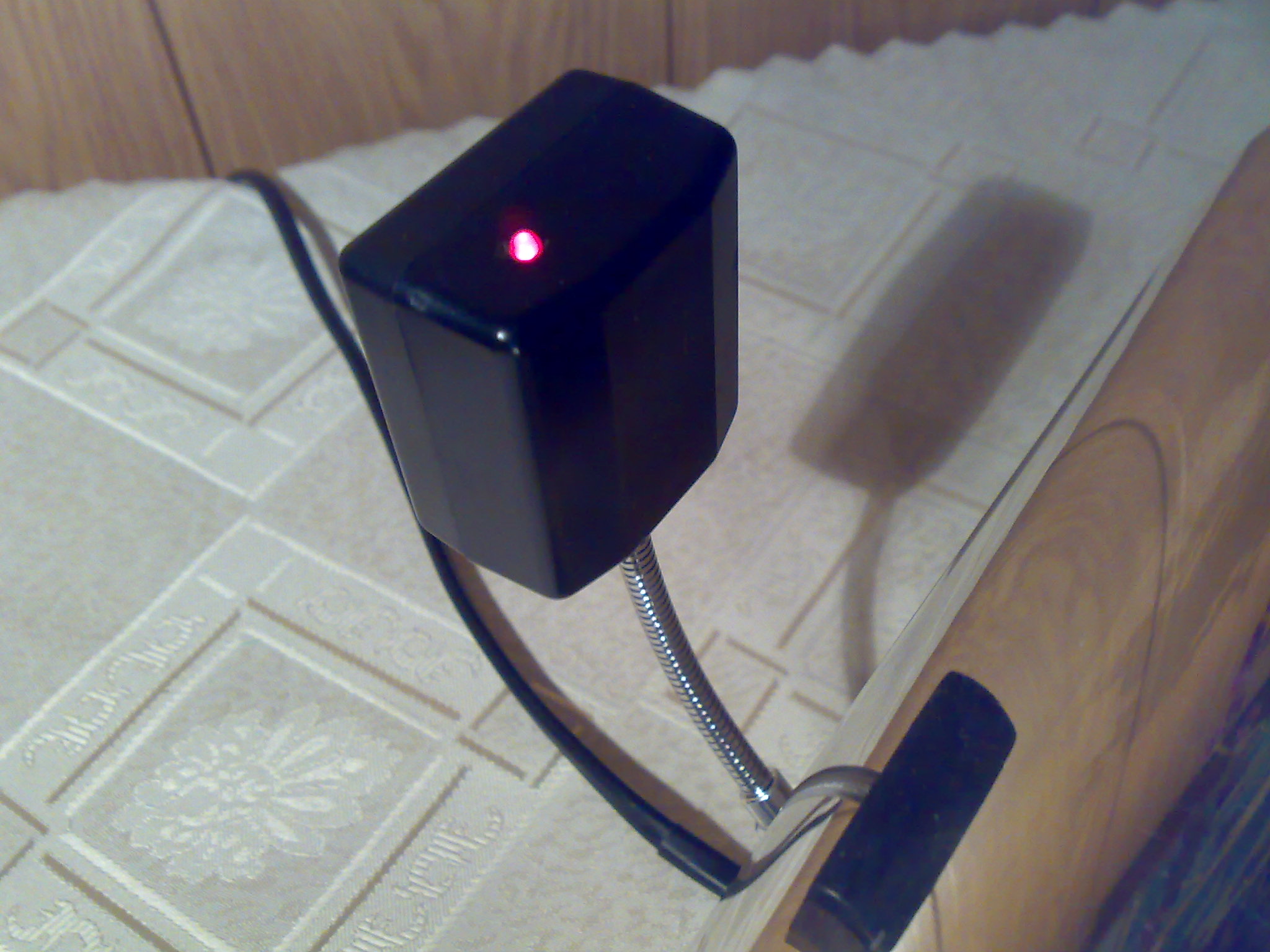
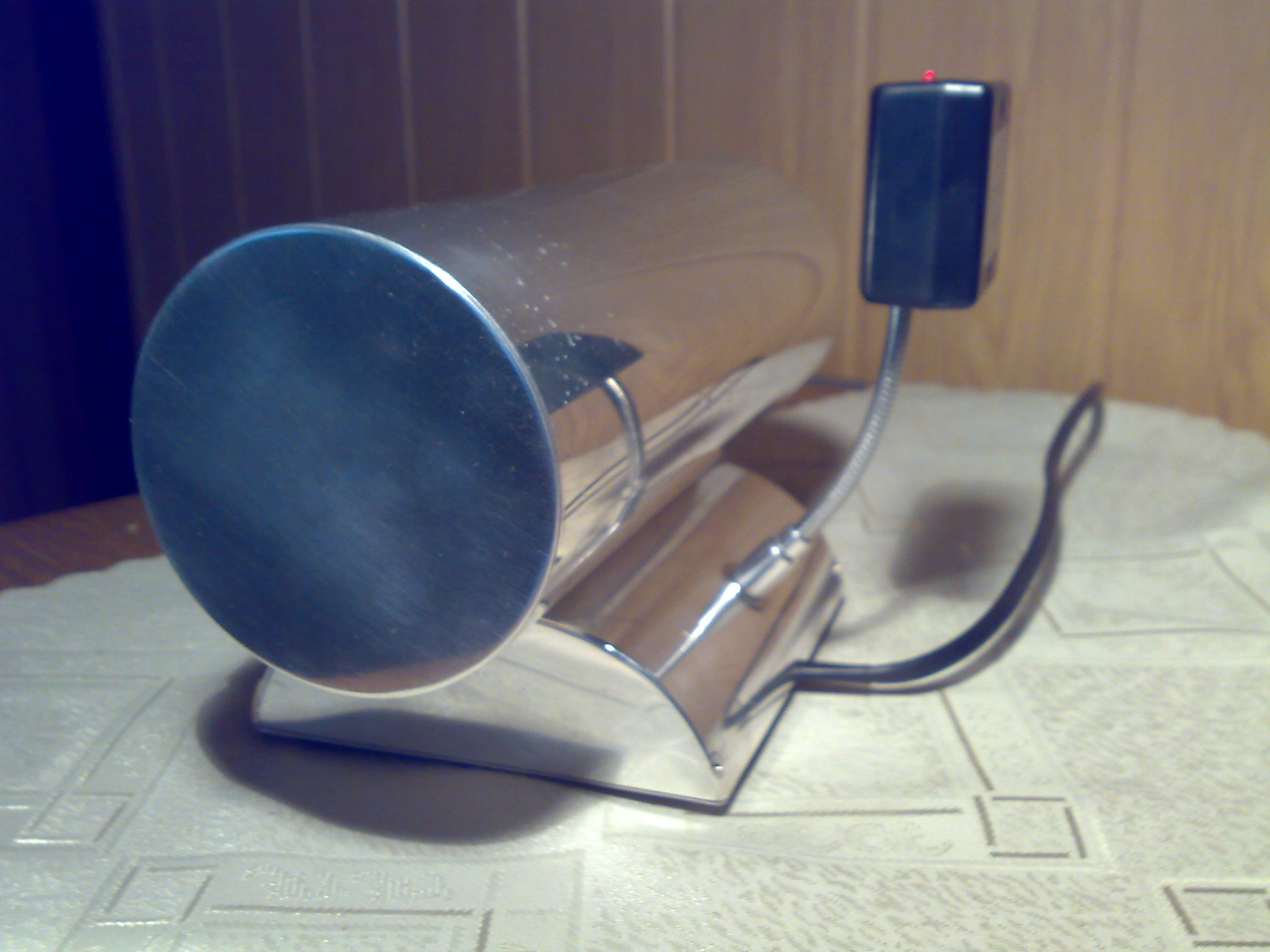
DCF receiver is based on system U4221B, which works with a short ferrite antenna (approximately 4cm). The whole is closed in a small box and mounted on an elastic leg. The whole is powered from a simple power supply on two small mains transformers.
And some pictures:


Link to original thread (useful attachment) – NIXIE LC-516 + DCF77
