Continue to Site

Welcome to EDAboard.com

Welcome to our site! EDAboard.com is an international Electronics Discussion Forum focused on EDA software, circuits, schematics, books, theory, papers, asic, pld, 8051, DSP, Network, RF, Analog Design, PCB, Service Manuals... and a whole lot more! To participate you need to register. Registration is free. Click here to register now.

NiCad Battery Discharge Circuit - Proteus ISIS

Status
Not open for further replies.

polisie

Newbie level 2
Joined
Jul 12, 2011
Messages
2
Helped
0
Reputation
0
Reaction score
0
Trophy points
1,281
Location
South Africa
Activity points
1,294
I am trying to build a NiCad Battery Discharge Circuit on Proteus ISIS Professional. The reason being is before i buy the components I want to see if the circuit is working. By trade i am a Mechanical Engineer and with little or no experience in the electronics world.

nicad_schematic.gif


Is the NiCad Battery Discharge Circuit OK?
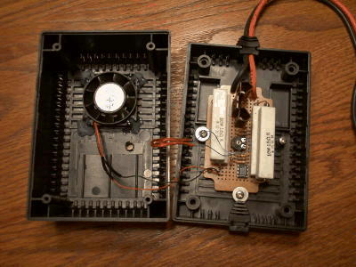
R6 is an 3.75 Ohm 40 Watt (four 15 Ohm 10W power resistors in parallel), in the pictures are these the big white blocks? if so I only see 2 and not 4.

nicad_layout.gif

nicad_inside.jpg


Any advice and help will greatly appreciated.

Thanks
Francois
 

in the pictures are these the big white blocks? if so I only see 2 and not 4.

Any advice and help will greatly appreciated.

Thanks
Francois
If you look closer at the last picture you will see the other hiding behind the top 2, basicily there 4 10w resistors wired in parallel so they can handle 40W, It's a cheaper way of doing it. The circuit looks fine to me, I would not trust ISIS on a circuit like this, The only thing you could simulate the the current, even then the current readings may be different in real life you cant feel the temp on a screen :-o. The down fall with ISIS is that the battery is a fixed voltage so it will never go below .9V. to test the switch off voltage. There is away but scrub that there is no model for the ICL7665

The way I would do it which may be an over kill is a PIC like 16F690 with LCD, this would display the actual runtime current and voltage, so you could turn the mosfet off once the end of discharge voltage has been reached, Also by using a pic you can keep the set current to a limit. This could also be used on fully charged batteries and monitor the run time and use it has a capacity tester to see how good your batteries are, This is the approach I would go
 

Thanks for the reply and sorting out my confusion. Agg think i will build it and see what will happen.
 

Status
Not open for further replies.

Part and Inventory Search

Welcome to EDABoard.com

Sponsor

Back
Top