Continue to Site

Welcome to EDAboard.com

Welcome to our site! EDAboard.com is an international Electronics Discussion Forum focused on EDA software, circuits, schematics, books, theory, papers, asic, pld, 8051, DSP, Network, RF, Analog Design, PCB, Service Manuals... and a whole lot more! To participate you need to register. Registration is free. Click here to register now.

Newby trying to learn more about oscilloscope.

Status
Not open for further replies.

Bucephalus

Newbie level 4
Joined
Apr 3, 2010
Messages
7
Helped
0
Reputation
0
Reaction score
0
Trophy points
1,281
Location
Queensland, Australia
Activity points
1,356
Hi there

I am just doing some basic tutorials so I can learn how to use the oscilloscope and signal generator.
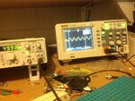
When it's on sine and sawtooth waveforms the waveform is relatively neat. But when I have it on square wave, the form of the wave is distorted. I have attached photos of the three waveforms.
Also, I have also compensated the probe on the square wave gen on the front of the oscilloscope.

Please can any one explain to me why this is happening? Is it normal? Is there a way I can improve on this signal representation?
Please see attachments of photos.

regards
David.
 

Attachments

  • sine_wave.gif
    sine_wave.gif
    227.5 KB · Views: 119
  • sawtooth_wave.jpg
    sawtooth_wave.jpg
    27.2 KB · Views: 103
  • distored_square_wave.gif
    distored_square_wave.gif
    279.3 KB · Views: 175

Have you connected the oscilloscope probe ground to the signal generator ground? That would be a possible cause of the spikes.

The sloping square waveform looks like you haven't adjusted the probe compensation. Connect the oscilloscope probe to the square wave output - the two terminals on the bottom right of the front panel of the oscilloscope - and adjust the small trim capacitor on the oscilloscope probe. The trimmer will be either on the lump with the connector on it or it could be at the probe tip end. Adjust it so the waveform is flat. Then look at the signal generator waveform again.

Keith
 

Set your 'Scope input to 'DC Coupled' for the square wave input.

What you are seeing in your pic is the effect of high pass filtering of the square wave caused by the low frequency bandwidth limit of AC coupling.
In simple terms, the low frequency part of the waveform 'droops' as a result of the filtering which causes the falling part of the trailing edge of the 'flat top' of a square wave.

hope this helps and that I haven't oversimplified too much
Mik
 

I see a coax going from your generator and a probe from your scope. If your signal is 50 Hz you better use DC coupling. But these effects also can occure (for most on higher frequency) if you use coax and not terminate that in to 50 Ohm. Better terminate it and then probe over the 50 Ohm.
The same if you connect the coax straight to the scope. Use an inline terminator on the scope input (the Rigol only has a 1M input. This 1M is not constant because it has a parallel capacitance. I once measured the Zin of a DS1102e and that dropped down to 31 Ohm at 100 Mhz. A terminator will improve things over the whole BW
 

Thanks for the advice Keith, Audio and PA4. I changed it over to DC coupling and it improved the signal to the first photo attached. However, there are still some spikes as you can see? Am I being overly ambitious in thinking these can be removed or attenuated? Or is it just something we all have to live with?

But these effects also can occure (for most on higher frequency) if you use coax and not terminate that in to 50 Ohm. Better terminate it and then probe over the 50 Ohm.
The same if you connect the coax straight to the scope. Use an inline terminator on the scope input (the Rigol only has a 1M input. This 1M is not constant because it has a parallel capacitance. I once measured the Zin of a DS1102e and that dropped down to 31 Ohm at 100 Mhz. A terminator will improve things over the whole BW

Regarding this issue. I have read a little about this 50 ohm termination and don't fully understand it, and why I haVe to do it, and how I do it. I found some 50 ohm BNC when I looked up this topic, so I'm thinking by what you mean as an "inline terminator" it's something that I connected between the coax and the signal generator. So please, why is it that I have to terminate over 50 ohm, and how does one terminate?

Also, now I'm having another issue with the oscope and the generator. When I have the generator on 5 or 50 hz the signal shows up fine, when I go to 500 and 5000 hz, the sine wave is aliased or something. It's another sine way 180 out of phase with the original wave overlaid over the top. See the photos below...what am I doing wrong here? I thought surely that my scope could handle 500 and 5000 hz

regards
David.
five_hertz.jpg fifty_hertz.jpg five_hundred_hertz.jpg five_thousand_hertz.jpg

- - - Updated - - -

Here the photo of the dc coupled square wave that you guys have helped me with. dc_coupled_small.jpg
 

Your generator is 50 Ohm, the coax cable is too. When you do not terminate it you get reflections in the cable. They show up as spikes. What you can try is probing direct in the outputconnector of the generator. Reflections is a part of the wave theory. You can use an inline terminator at the scope input. More expensive scopes often have a build in 50 Ohm termination.

The problem you have now looks like you have the trigger wrong. Press auto in the right top corner to see if it goes away

An other thing DSOs can do has to do with sampling. If the timebase is to slow for the signal it will make up some waveform . Try this: put a 1 MHz wave on the screen. Set the timebase so it shows f.i. about 5 periods or so (does not matter how much excact). Now change the timebase to be slower. You will see more waveforms. If you go on you will see them change in to a "block" They are so close together you can not see individual waveformns anymore. If you go on you will first see the "block" starts to look like an AM modulated signal. It gets the shape of a sinewave on the top and bottom. And if you go even further suddenly that goes away and you get a sinewave with a very low frequency. This is something only samplescopes do. Analog or digital.
 

Status
Not open for further replies.

Similar threads

Part and Inventory Search

Welcome to EDABoard.com

Sponsor

Back
Top