Continue to Site

Welcome to EDAboard.com

Welcome to our site! EDAboard.com is an international Electronics Discussion Forum focused on EDA software, circuits, schematics, books, theory, papers, asic, pld, 8051, DSP, Network, RF, Analog Design, PCB, Service Manuals... and a whole lot more! To participate you need to register. Registration is free. Click here to register now.

new types of PIC programming for push buttons interface

Status
Not open for further replies.

john120

Banned
Full Member level 5
Joined
Aug 13, 2011
Messages
257
Helped
11
Reputation
22
Reaction score
10
Trophy points
1,298
Visit site
Activity points
0
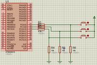
Hello every bosy here is an attachment of buttons which are causing me many confusion,I want to replace that AT90S8515 by a PIC16F877A so the problem I have is that the buttons which I am using are not reacting at all.
That schematic above gives what was in the first device using the same buttons but now I am trying to implement the same the buttons are not reacting;what can I do;is there an other manner of connecting buttons so they can react easily.

Those above are also connected on 1N4148 diode which are controlled by a BJT Transistor whith base is on level high always.

Can you help me to think far on buttons.

Thanks
 

Attachments

  • forum1.zip
    4.8 KB · Views: 79

Hi,

This is a more normal way of connecting a switch.
 

Attachments

  • 000014.jpg
    000014.jpg
    50.8 KB · Views: 111

Hi,

This is a more normal way of connecting a switch.

Perhaps it might be normal but with the buttons which I want to use are not working but when I connect those buttons on the first circuit (on which they made in industry together )they operate very well.

Thanks
 

when button is open it is floating and will not work so use pull down resistor as nagakiller said.
 

When open, the button is at 0V when closed + V(5V).
The pull down or pull up is just to force the level in pin!!!
Only make the condition of the button in your program!!!
Works perfectly!!!
 
Last edited:

When open, the button is at 0V when closed + V(5V).
The pull down or pull up is just to force the level in pin!!!
Only make the condition of the button in your program!!!
Works perfectly!!!

on my schematic those grounding resistors are replaced by 1N4148 diodes and they are placed after those resistances which are in serie with the buttons.
How may I use pull up resistors in ccs c compiler?
Please help on this.

Thanks!!!
 

External or Internal???
Internal using port_B_pullups(0xFF);!!!
External I recommend using resistor in place of the diodes, like example of wp100 (pull up resistor) or my example (pull down resistor)...

If use PullUp resistor like example wp100 you use:

Code:
if (!input(PIN_A4))  //  PIN_A4 change from VCC to GND
{

}

Or example pulldown:

Code:
if (input(PIN_A4))  //  PIN_A4 change from GND to VCC
{

}
 
Last edited:

External or Internal???
Internal using port_B_pullups(0xFF);!!!
External I recommend using resistor in place of the diodes, like example of wp100 (pull up resistor) or my example (pull down resistor)...

pic mcu don't have pull down resistors internally,you can use only pull up resistor though.
 

Yes!!! Only PullUps!!! (as see in example)
So the example like wp100 is the most used!!!
Post your project!!! Schematic and Code!!!
 
Last edited:

Status
Not open for further replies.

Similar threads

Part and Inventory Search

Welcome to EDABoard.com

Sponsor

Back
Top