Continue to Site

Welcome to EDAboard.com

Welcome to our site! EDAboard.com is an international Electronics Discussion Forum focused on EDA software, circuits, schematics, books, theory, papers, asic, pld, 8051, DSP, Network, RF, Analog Design, PCB, Service Manuals... and a whole lot more! To participate you need to register. Registration is free. Click here to register now.

Neutral point clamped inverter: driver ir2110 problem

Status
Not open for further replies.
Can you show us the circuit you used? when you do the proper timing then what is the point in relying on some external unknown delay?

* Circuit used before for three phase 2 level IGBT inverter.
* no timing can be implemented in software as it is just less than 10 micro-seconds
* delay is not external unknown. delay is internal function in IRxx to prevent short circuiting the "H" and "L" IGBTs at the same inverter leg TIP-IGBT driver.jpg
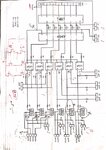
 

no timing can be implemented in software as it is just less than 10 micro-seconds

What is your switching(PWM) frequency ? Remember that already you are getting 10uS delay(switch ON and OFF) in opto stage you are using.

Also remember that you are putting 330ohm in series with Gate, which will increase your switching time. Incase of IR2110 it will supply 2.0A gate current.
 

The switching frequency is up to 3 KHz. regarding opto delay is same for all IGBT so no time delay shift is there between both IGBT in same leg.
 

The thing is we cant assure that with IR2110 your configuration will work without any problems. It has more disadvantages than advantages. The main advantage would be its totem pole driver configuration.

opto delay is same for all IGBT so no time delay shift is there between both IGBT in same leg
But they are need not to be same when it comes to switching ON and OFF timing. Are you bringing the Q2, Q3 ON for every intermediate 0V conditions ? I have already worked in 18kHz switching scheme with transistors and didnt got into any of this problems. Also you can try with a PNP transitor driver circuit which will eliminate the switching losses.

The best solution should be a individual driver (may be in IR series itself with totem pole configuration) for every IGBT.
But still we can not say sure that your IR2110 will not work in a practical circuit.
 

for the clamped mode, yes Q2&Q3 will be on. for the timing issue, with high power application and +400Vdc, short circuit definitely will take place for few microseconds but when supplying inductive load, that time will prolong and IGBT will be stressed till get damaged.
I have no other circuit else the TIP one which can be extended to adapt the NPC configuration. would you suggest that.
 

I will test IR2110 once I completed the hardware setup and provide the results, then we can have a conclusion.
 

Status
Not open for further replies.

Similar threads

Part and Inventory Search

Welcome to EDABoard.com

Sponsor

Back
Top