Welcome to our site! EDAboard.com is an international Electronics Discussion Forum focused on EDA software, circuits, schematics, books, theory, papers, asic, pld, 8051, DSP, Network, RF, Analog Design, PCB, Service Manuals... and a whole lot more! To participate you need to register. Registration is free. Click here to register now.
Use a SMPS front end, taking in -48V and converting it to a 48V squarewave, pass this through a transformer and adjust the turns ratio to give you 12 V, then use a diode bridge to get to 12V, earth which ever lead you want.
Frank
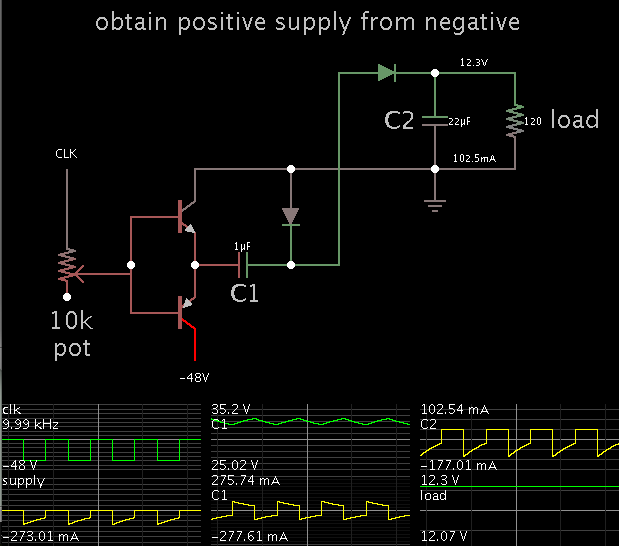
Is your plan to obtain a positive supply from a negative supply?
A half-bridge driving a charge-pump capacitor is one of the simpler methods.
The step-down effect is achieved by (a) using a small value for C1, and/ or (b) adjusting bias to the transistors so they conduct a limited amount of current.
The transistors each drop several volts. They may get hot, depending on how much current your load draws.
This method is probably suitable only in cases where you need just a fraction of an ampere.
I would expect there are plenty of telecom-standard DC-DCs
made to operate in a -48V system, and an isolated-output
one doesn't really care where you pin the output reference
ground. Right? Have you looked simply for 48V-12V isolated
converters and checked whether this is viable, for a particular
one?
This site uses cookies to help personalise content, tailor your experience and to keep you logged in if you register.
By continuing to use this site, you are consenting to our use of cookies.