bijaypaudel
Member level 1

- Joined
- Dec 14, 2011
- Messages
- 32
- Helped
- 4
- Reputation
- 8
- Reaction score
- 4
- Trophy points
- 1,288
- Activity points
- 1,489
Here's the problem:
the pulses are for providing Gate signal to GTO....
i have used two ports from microcontroller(pic16f877) as outputs RC1 and RC2, and they are connected to a circuit that gives single output line.
the circuit should give output 0v when Rc1=0 and +5v or -5v when RC1=0 as per value of RC2(0,1)...
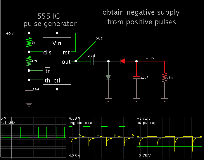
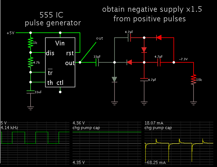
can charge pump circuit can be interfaced with uc to get requirement!!!!
the pulses are for providing Gate signal to GTO....
i have used two ports from microcontroller(pic16f877) as outputs RC1 and RC2, and they are connected to a circuit that gives single output line.
the circuit should give output 0v when Rc1=0 and +5v or -5v when RC1=0 as per value of RC2(0,1)...
can charge pump circuit can be interfaced with uc to get requirement!!!!