Continue to Site

Welcome to EDAboard.com

Welcome to our site! EDAboard.com is an international Electronics Discussion Forum focused on EDA software, circuits, schematics, books, theory, papers, asic, pld, 8051, DSP, Network, RF, Analog Design, PCB, Service Manuals... and a whole lot more! To participate you need to register. Registration is free. Click here to register now.

[SOLVED] Need to reuse my 12V 2amp DC adapter as an input to 7805 IC

Status
Not open for further replies.

AdityaRajNayak

Junior Member level 1
Joined
Dec 8, 2013
Messages
15
Helped
5
Reputation
10
Reaction score
5
Trophy points
3
Location
India
Activity points
118
I have a 12V 2Amp DC Adapter. I have designed a power supply circuit using 7805(without heat sink). I want to give the output of the adapter as the input to this power supply circut. But as per my study 7805 shuts down in case current goes beyond >600 mA, and so the output at 7805 is not 5V(Please correct if my understanding is incorrect). Request to suggest some circuit I could use inbetween the Adapter and Power Supply circuit so that I can reduce the current upto atleast 1A~.5A so that it becomes useful for 7805.

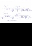
Below is the block diagram:

<12V/2A DC Adapter > --------- <?? Circuit ??> ----------< Power Supply circuit with 7805 IC that can tolerate max .5A without Heat Sink>

[Query] Need help on <?? Circuit ??> in the above diagram.
 

You don't want to reduce the current, you want to reduce the voltage but in any case the 7805 will overheat without a heatsink. The power it dissipates is the voltage across the input and output terminals multiplied by the current through it "(VIN - VOUT) / I" and there is nothing you can do to stop that. If you are providing 12V from the adapter and you want to take 1A from the 7805 it is producing (12-5)/1 = 7 Watts of heat. If you want to run a 7805 without a heat sink I would suggest you keep the dissipation below about 0.25W.

The best you can do without getting into complicated circuits is add a resistor in series with the adapter output. The resistor has to drop 12V down to the voltage needed at the input of the 7805 for it to remain capable of regulating 5V at it's output, in most cases they need around 3V overhead so you want 8V at the input pin. So the resistor has to drop 12V to 8V at 1A, Ohms law says R=V/I so you need (12-8)/1 = 4 Ohms. The resistor will get hot though, it is going to waste the heat that the 7805 would otherwise lose. It will dissipate VxI = 4 x 1 = 4 Watts so you need a resistor of 5W rating or higher to give it a safety margin.

Note that the resistor and regulator produce heat proportional to the current you draw, the calculations are for maximum current (1A) so in reality it may not get as hot as predicted.

Don't forget to add a capacitor across the input and ground pins of the 7805 as recommended on the data sheet, this is particularly important if you add the resistor.

Brian.
 
Thanks Brian,
for suggesting the circuit regarding addition of 5W resistor.
I am attaching the circuit diagram for the existing circuit and the modified one for confirmation.
 

Attachments

  • Image.jpg
    Image.jpg
    133.2 KB · Views: 77

That is correct. Please bear in mind that all linear regulators like the 7805 produce heat, it will still get hot when under load but that extra resistor will sightly reduce the total heat produced and will share it with the 7805.

Brian.
 
Status
Not open for further replies.

Part and Inventory Search

Welcome to EDABoard.com

Sponsor

Back
Top