Continue to Site

Welcome to EDAboard.com

Welcome to our site! EDAboard.com is an international Electronics Discussion Forum focused on EDA software, circuits, schematics, books, theory, papers, asic, pld, 8051, DSP, Network, RF, Analog Design, PCB, Service Manuals... and a whole lot more! To participate you need to register. Registration is free. Click here to register now.

Need to remove a Relay from a timer circuit.

Status
Not open for further replies.

Diy-Fiero-Stu

Newbie level 3
Joined
Feb 13, 2007
Messages
4
Helped
0
Reputation
0
Reaction score
0
Trophy points
1,281
Activity points
1,311
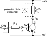
I have a simple 555 timer circuit that I need to remove the relay from. Reason for this is #1 magnets in area affecting reliability and #2 lessen cost. The load is Aprox 1A @12Vdc but I want to have at lest 1.25A capability. I figure the TIP31 would be a good canadate since I will be switching the positive leg of the load. Here is a schematic of what I have can you assist me in removing the relay and inserting the transistor? I never studied much about transistors yet now I wish I had.

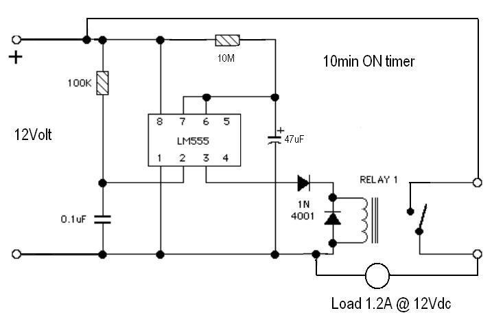
555 says 200ma Max load on output pin 3.

21_1171335219.JPG
 

You need the 555 12v output to drive small N transistor like 2n2222 or N FET 2n7000
The N transistor / N FET connected as inverter driver to power P FET so the 555 12v output will switch on the power P FET on
 

The circuit I have built uses the 555 to hold power to the relay for 10 minutes then release. Once it releases it won't turn back on until power is removed then replaced. This is where I'm having troubles is you can actually hear the relay click but to power flows through it.

Added after 2 hours 13 minutes:

Would there be a much simpler method if it didn't matter which side of the load was switched?

Output goes High for 10 minutes on teh 555 then goes low until reset. Load must receive 1.3A @12VDC when the 555 is High.
 

If you can, move load from negative pole to positive pole and then you can use TIP31 as a switch .. see picture below ..

Regards,
IanP
 

Attachments

  • 555-npn-load_6874.gif
    555-npn-load_6874.gif
    3.8 KB · Views: 141

Using the TIP31 is what I would like to do but will I need to drive the TIP31 with another Transistor due to the limited 555 output of 200ma MAX? Since the output of the TIP31 will need to be 1.3A at12V?
How do I figure the resistor needed between the 555 output and the TIP31? The load is just a Lamp that draws 970mA but some could dray over an Amp so I want 1.3 aAmp capability without damage.
 

TIP31 is a darlington ..
Typically, for 6A the Collector current it needs roughly 30mA of the Base current ..
You can drive it directly of 555 timer - something like Rb=300Ω (100-470) will do ..

Regards,
IanP
 
Status
Not open for further replies.

Similar threads

Part and Inventory Search

Welcome to EDABoard.com

Sponsor

Back
Top