Continue to Site

Welcome to EDAboard.com

Welcome to our site! EDAboard.com is an international Electronics Discussion Forum focused on EDA software, circuits, schematics, books, theory, papers, asic, pld, 8051, DSP, Network, RF, Analog Design, PCB, Service Manuals... and a whole lot more! To participate you need to register. Registration is free. Click here to register now.

[SOLVED] Need some information about TA1309-200

Status
Not open for further replies.
TA1309-200
Rated Input Current = 5.0 A
Frequency = 20Hz ~ 20KHz
Nano Crystalline Epoxy High High Accuracy
Measuring Range = 0~5 A
Ratio = 2000:1
Sampling Resistance = 800Ω
Sampling Voltage = 2V
Voltage Phase Shift = ≦ 10V
Non Linearity = ≦ 0.2%

I hope this helps.
 
No I do not have but it is very simple to identify. Just measure the resistance of both sides. Input side will be Zero and output side will have much higher resistance. Even when you see the pins you can identify them, input will be Thick Pins and output Thin Pins. If still doubt upload the trafo image, I may indicate for you.
 

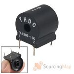
ta1309100-zero-phase-mini-current-transformer-130103n.jpg

This is what I was talking about. Can you tell me what is the diagram for this? And as I need to sense the voltage with MCU so I need a perfect calculation. Do you have any data for this?
 

But this is 1309-100 not 1309-200. Both differ in specs. 1309-100 has ratio 1000:1.
You can see the direction of current flow. I will post for you a sample circuit of usage as soon as I am free a bit. Will post rest of the specification, too, of 1309-100.
 

Raza can you tell me.........the output voltage of this CT is DC or AC ?
 

Status
Not open for further replies.

Similar threads

Part and Inventory Search

Welcome to EDABoard.com

Sponsor

Back
Top