Continue to Site

Welcome to EDAboard.com

Welcome to our site! EDAboard.com is an international Electronics Discussion Forum focused on EDA software, circuits, schematics, books, theory, papers, asic, pld, 8051, DSP, Network, RF, Analog Design, PCB, Service Manuals... and a whole lot more! To participate you need to register. Registration is free. Click here to register now.

Need practical advices on vibration testing...

Status
Not open for further replies.

powersys

Advanced Member level 1
Joined
Nov 29, 2005
Messages
439
Helped
3
Reputation
6
Reaction score
2
Trophy points
1,298
Activity points
4,981
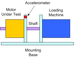
I wish to measure the vibration of an electric motor as shown in figure below. One of the accelerometers (red) is placed at the location as shown in the figure. The accelerometers are manufactured by PCB. They are connected to a power unit and from the power unit their signals are fed to Agilent Dynamic Signal Analyser 35670A for frequency domain analysis using FFT.

A vibration peak is expected to be observed at frequency 500Hz. The number of average measurement taken is 20. I manage to measure this peak.

I repeat the test, with similar setup, settings, and assembly program, many times (morning, afternoon, night; monday, tuesday,...etc). The accelerometer was never removed from the setup and it was at the same location in all those tests. I found the amplitude of the peak at 500Hz is not consistent. The lowest measured value is 110 (uVrms), whilst the highest value can be up to 160 (uVrms). The supply to the load machine was monitored closely so that it exerted a constant load to the motor under test. In my opinion, the difference (50uVrms) is too high and I suspect something wrong with my experiment. But I could not find out the causes of the inconsistency. Therefore, I will really appreciate if you guys can share your practical experience when performing vibration test with accelerometer.

97_1261530702.png


By the way I wish to understand more the following issues. Kindly advise which reference book that covers the following subjects.

PRACTICAL ISSUES

3.1 Selecting the right parameter
3.2 Problems in simple usage (portable monitoring with vibration meter or data collector)
3.3 Repeatability (portable monitoring)
3.3.1 Non-repeatability due to machine condition
a. Background vibration
b. Effect of machine speed and load, etc.
c. Variation of signal at nominally constant operating conditions Time domain averaging Process domain averaging
d. Trending of data
3.3.2 Non-repeatability due to measurement technique
a. Mounting of transducer
b. Temperature effects
c. Spurious low frequency 'Ski-slope' effect
d. Saturation of the conditioning electronics
3.4 Experience with permanent monitors
3.5 Implementation of permanent monitors

Thank you very much
 

I always look at machine vibration in g's or m/s^2. The voltage of signal is dependand on the equipment taking the measurement cable and acceleratometer

you also need base line readings when nothing is running. As well as harmonic base lines.

For any other thoughts I would need to know size of motor in hp operating condition. shaft, coupling, and load device and operation speed.

I could recomend some nice classes but very expensive. but I don't know any books that I like as a learning text for vibration specific issues.

My answer kind of assumes we're discussing large industal machery, as apposed to something cheap, can be kept on site in stock and disposable.
 

    powersys

    Points: 2
    Helpful Answer Positive Rating
well, there are two possible explanations:
1) the way you are taking the measurements is not consistent. Maybe you are sampling the signal, but in such a way that there is aliasing going on, and you get different results with each sample set. Increase your sample rate and see if the data remains stable
2) The amount of vibration energy varies over time. It might be "throbing" between a low vibration state and a high vibration state. Causes could be two different vibration sources "beating" against each other (like you would hear in a two engined airplaine where the two RPM's are not fully synchronized). Another possibility is a resonance (physcially large metal stucture, etc) that resonates around 500 Hz. Your input vibration might be "beating" with the structure that is resonating, for instnace.

In my experience (measuring vibration effects on electronic circuits), one has to spend a whole lot of time making sure the mounting mechanism you are using in itself does not have resonant frequencies, since any fixture resonances will confuse if the circuit board is resonating or not. You might have the same concern--somehting in the mounting plates, screws, etc, that is resonating at 500 Hz.
 

    powersys

    Points: 2
    Helpful Answer Positive Rating
ccccrnr said:
I always look at machine vibration in g's or m/s^2. The voltage of signal is dependand on the equipment taking the measurement cable and acceleratometer

you also need base line readings when nothing is running. As well as harmonic base lines.

For any other thoughts I would need to know size of motor in hp operating condition. shaft, coupling, and load device and operation speed.
Thanks for your reply. A more elaborate setup drawing is given below. The readings given in my first post has not been scaled to proper unit. I have checked the base line readings and they look normal and consistent.

The motor under test is fractional hp permanent magnet brushless motor (about 250Watts). The coupling "M" is a bellow-type, whilst the coupling "N" is a resilient type. 500rpm is the rated speed of the motor. The loading machine is in fact a separately-excited DC machine (field winding is connected to a constant Vdc, whilst it's armature winding is connected to a resistive load).


Added after 28 minutes:

biff44 said:
well, there are two possible explanations:
1) the way you are taking the measurements is not consistent. Maybe you are sampling the signal, but in such a way that there is aliasing going on, and you get different results with each sample set. Increase your sample rate and see if the data remains stable
2) The amount of vibration energy varies over time. It might be "throbing" between a low vibration state and a high vibration state. Causes could be two different vibration sources "beating" against each other (like you would hear in a two engined airplaine where the two RPM's are not fully synchronized). Another possibility is a resonance (physcially large metal stucture, etc) that resonates around 500 Hz. Your input vibration might be "beating" with the structure that is resonating, for instnace.

In my experience (measuring vibration effects on electronic circuits), one has to spend a whole lot of time making sure the mounting mechanism you are using in itself does not have resonant frequencies, since any fixture resonances will confuse if the circuit board is resonating or not. You might have the same concern--somehting in the mounting plates, screws, etc, that is resonating at 500 Hz.
Thanks for your reply. Kindly observe the experiment results (amplitude of 500Hz peak) below, which are taken at different times and different days with similar experimental setup and test conditions.

[2009-12-02]
5.00pm - 104 (measured at 5pm and the reading is 104)
6.40pm - 119
8.13pm - 126

Three measurements were taken each time. For example, at 5.00pm, the motor was started and a measurement was taken. Then, the motor was stopped, and restarted again. Another measurement was taken. The same procedure repeated for the third measurement. Each measurement took about one minute. The average value (i.e. 104, which is rounded to integer) of three readings was given above. Kindly note that all the three measurements taken (at each specific interval) were very close to the average value (±2). The same number of measurement was taken at 6.40pm and 8.13pm. More results as follows:

[2009-12-03]
1.30pm - 127
7.37pm - 135

[2009-12-04]
1.51pm - 131
2.30pm - 125

[2009-12-05]
2.16pm - 107
3.01pm - 117
8.44pm - 134

As you can see, the error in measurement can go up to 30uVrms. Sometimes, as I mentioned in my first post, can go higher. Kindly advise the causes of these inconsistency.

By the way, do you think I should the "ground input" at the rear panel of the Agilent 35670A? If YES, should I connect it the body of the motor mounting? The accelerometer used in the test is PCB 303A03.
**broken link removed**
The PCB 303A03 is attached to the mounting using wax. Therefore, I assume there might a "short-circuit" between the accelerometer casing and motor mounting.

Thanks.

Agilent 35670A Front Panel


Agilent 35670A Rear Panel
 

Factors that will influence the RMS (narrow or braod band) are:

Temperture
Other process related noise
The way you take the FFT. (FFT bin size)
Sinc the capturing of the time domain wave form to start at the same shaft angle

Please see tha attached graphs at mx2.motornostix.co.za login with username demo and password demo. Download components; GOTO mimic of Condenser 1 or 2 and tick vibration channels for graphs[/img]
 

Status
Not open for further replies.

Part and Inventory Search

Welcome to EDABoard.com

Sponsor

Back
Top