Continue to Site

Welcome to EDAboard.com

Welcome to our site! EDAboard.com is an international Electronics Discussion Forum focused on EDA software, circuits, schematics, books, theory, papers, asic, pld, 8051, DSP, Network, RF, Analog Design, PCB, Service Manuals... and a whole lot more! To participate you need to register. Registration is free. Click here to register now.

need power supply solution

Status
Not open for further replies.

vishu489

Advanced Member level 4
Joined
Aug 28, 2011
Messages
116
Helped
3
Reputation
6
Reaction score
3
Trophy points
1,298
Activity points
2,120
hello friends,

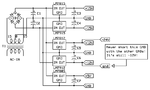
Now i'm designing 4-20 ma current receiver by using RCV420.

I need Following O/p voltages
+24vdc -> for transmitter
+12vdc -> For relay
+5v -> for microcontroller
+15v & -15v dc -> for rcv420

my i/p to power supply section is 110-230vac mains

can you help me in designing power supply section?
also is it possible to operate rcv420 at+/- 12v dc rather that +/-15 vdc?

waiting for your reply
 

use a small transformer to transform the AC mains to around 25v
then add a 4 diode bridge to rectify the signal then add capacitors to smoth the output. you will get the 24v
then use a 15v voltage regualor (7815) , and a negative regulator 7915 for -15v
then use a 12v and voltage regulator like (7812) , you will get 12v , then after this regulator use a 7805 regulator to get the 5v .

for the current you are using i donot think heat dissipation is a problem hence , heatsinking is not required

hope this helps , if you need more clarrification , ask :)
 
Thanks for your reply

Can you tell me any IC which can give me dual supply of +/-12v or +/-15v dc ?

I think it will save my time and pcb space.

waiting for
 

Thanks for your reply

Can you tell me any IC which can give me dual supply of +/-12v or +/-15v dc ?

I think it will save my time and pcb space.

waiting for

your welcome
from linear technology:
LT3032MPDE-15 (+/-15)
and LT3032EDE-1 (+/-12)
 
can you provide me any example schematic, since i'm not having any experience of designing ac to dc transformer based power supply. I usually use adapter, but for this part i want to do it by using transformer
 

I still prefer the using 2 regulators 1 for +15v and another for -15v , since the regulator that does both is not very common and a bit expensive and i donot have its model.


SO this is the schematic i draw for you , note that it is a rough schematic you may need to add extra capacitors for filtering and note the polarity of the 7915 it is the opposite of the rest ( Vin (pin2 to gnd of the circuit, and GND (pin 1) to 24v) check datasheet .

https://obrazki.elektroda.pl/9059498200_1367526874.png

i have also added another pic for a schematic i found that is for +/-15v only with lots of filtering and protection. and clarification of regulators connection

https://obrazki.elektroda.pl/6307532600_1367526918.jpg

note also that the transformer has to be about 10:1 for 220v ac , and 5:1 for 110ac

hope that helps
 
Thank you for your reply.

I will try it and i will let you know about it.
 

Can you specify more details about transformer.
I mean which type of transformer I have to buy?
 

What you need to do first is understand what it is you need. You have listed only voltages, but you need to know also how much power (mA) is required for each rail, what accuracy is required, if efficiency is something to consider, what level of complexity you are willing to accept, whether you are capable of using a switchmode solution, if system cost is a consideration etc.

That said, one hint I might give is to choose a relay that operates @24V. Would save you one voltage rail ;)
 

you need to specify a amps range in your power supply, then only you could choose the transformer range..
 

Posting just to say that if you want +/-12V and +24V, you can use the same +/-12V lines by considering -12V as GND and +12V as +24V (the voltage between them is exaclty 24V). This way you can save a power line and you'll easily find a 12-0-12 transformer rather than one with 24V. Moreover, you said you need +/-15V too; if you buy a 15-0-15 transformer it will give you the +/-15V directly (just rectify the current using a 4 diode bridge), then you can use some fixed voltage regulators to get +/-12V. Once done that you'll have +/-15V, +/-12V and 24V as junction between -12V and +12V.
Oh, you'll be able to get 5V from the 15V power line using a 5V fixed voltage regulator.

I hope it helps :)

EDIT
I made a very very simple linear power supply circuit using the famous LM78xx and LM79xx fixed voltage regulators. This circuit needs a dual 15V output (15-0-15) transformer with 60W power for full power operation on the low current versions of the ICs (max 1A for each IC), and 180W for full operation on the high current versions (max 3A for each IC) - Obviously, these are the maximum ratings, you should calculate the amount of power needed to supply your circuit and properly calibrate it.
The ICs need to be placed on a big heatsink because they'll heat a lot. The ICs accept up to 35V input before breaking, so if you get a slightly higher voltage output from the transformer (say 25-0-25) it'll still be fine but consider that higher voltages also cause more heat on the ICs.
I say again: this is a very very simple circuit, so there's no protection against any issues you could run into; short circuits will damage the ICs. Any electronic noises coming from the components using this power supply may affect the others in a considerable manner, and any damage from a component can lead to the damage of the others.
Also, VERY IMPORTANT: I told you can use the +12V and -12V as the 24V power line. As you can read on the schematic, never short circuit the main GND of other ICs with the gnd of the 24V power line: In fact, the 24V power line gnd is still the -12V line, and shorting it to GND will cause a short circuit between the main GND and -12V!! Be very careful!

Components:
T1: Transformer, 15-0-15 output, 60W *1, 180W*2
DB1: Diode Bridge, 5A up to 10A
C1, C2: Electrolytic capacitors, 25V (or higher, depending on the transformer output), 1000uF (or higher value up to 2200uF)
C3, C4, C5, C6, C7: Electrolytic, 25V, 47uF
IC: LM7815 (+15V), LM7915 (-15V), LM7812 (+12V), LM7912 (-12V), LM7805 (+5V)

*1 Calibrated for 1A output on each IC (low current ICs)
*2 Calibrated for 3A output on each IC (high current ICs)
 

Attachments

  • PowerSupply.png
    PowerSupply.png
    30 KB · Views: 72
Last edited:

Status
Not open for further replies.

Similar threads

Part and Inventory Search

Welcome to EDABoard.com

Sponsor

Back
Top