Continue to Site

Welcome to EDAboard.com

Welcome to our site! EDAboard.com is an international Electronics Discussion Forum focused on EDA software, circuits, schematics, books, theory, papers, asic, pld, 8051, DSP, Network, RF, Analog Design, PCB, Service Manuals... and a whole lot more! To participate you need to register. Registration is free. Click here to register now.

[SOLVED] Need help with the finite state machine

Status
Not open for further replies.

owenljn

Newbie level 6
Newbie level 6
Joined
Feb 14, 2013
Messages
14
Helped
0
Reputation
0
Reaction score
0
Trophy points
1,281
Visit site
Activity points
1,401
Here's the question:

We wish to implement a nite state machine (FSM) that recognizes two speci c sequences of applied input
symbols, namely four consecutive 1s or four consecutive 0s. There is an input w and an output z. Whenever
w = 1 or w = 0 for four consecutive clock pulses the value of z has to be 1; otherwise, z = 0. Overlapping
sequences are allowed, so that if w = 1 for ve consecutive clock pulses the output z will be equal to 1 after the
fourth and fth pulses. Figure 1 illustrates the required relationship between w and z.
clock.png

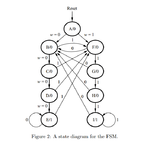
A state diagram for this FSM is shown in Figure 2.
fsm.png

table.png
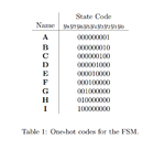
Write a Verilog file that instantiates the nine flip-flops in the circuit and which speci es the logic expressions
that drive the flip-flop input ports. Use only simple assign statements in your Verilog code to specify
the logic feeding the flip-flops. Note that the one-hot code enables you to derive these expressions by
inspection.
Use the toggle switch SW0 on the DE2-series board as an active-low synchronous reset input for the
FSM, use SW1 as the w input, and the pushbutton KEY0 as the clock input which is applied manually.
Use the green light LEDG0 as the output z, and assign the state flip-flop outputs to the red lights LEDR8
to LEDR0.


Here's my code, it works for transitions from A to H, but when I press clock after H, the state stay at state H and won't go to state I, can anyone help me fix this code??

Code:
module part1(SW, KEY, LEDG, LEDR);

	input [1:0] KEY, SW;
	output [1:0] LEDG;
	output [17:0] LEDR;

	reg  z;
	reg [3:0] shifter;
	reg [8:0] Y;

	always @(posedge KEY[0] or posedge SW[0]) begin
		if (SW[0]) begin
			z <= 1'b0;
			shifter <= 4'b0101;
			Y <= 9'b000000001; // A
		end
		else begin
			if (shifter == 4'b0000)
				z <= 1'b0;
			else if (shifter == 4'b1111)
				z <= 1'b1;
			else
				if ((shifter == 4'b0110)|(shifter == 4'b1110)|(shifter == 4'b0010)|((shifter == 4'b0101)&~SW[1]))
					Y <= 9'b000000010; // B
				else if ((shifter == 4'b1010)|(shifter == 4'b1100))
					Y <= 9'b000000100; // C
				else if (shifter == 4'b0100)
					Y <= 9'b000001000; // D
				else if ((shifter == 4'b0000)|(shifter == 4'b1000))
					Y <= 9'b000010000; // E
				else if ((shifter == 4'b0001)|(shifter == 4'b1101)|(shifter == 4'b1001)|((shifter == 4'b0101)&SW[1]))
					Y <= 9'b000100000; // F
				else if ((shifter == 4'b0011)|(shifter == 4'b1011))
					Y <= 9'b001000000; // G
				else if (shifter == 4'b0111)
					Y <= 9'b010000000; // H
				else if (shifter == 4'b1111)
					Y <= 9'b100000000; // I
			shifter[3:0] <= { shifter[2:0] , SW[1] };
		end
	end

	assign LEDG[0] = z;
	assign LEDR[8:0] = Y;
	assign LEDR[17:14] = shifter;
endmodule
 
Last edited:

Here's my code, it works for transitions from A to H, but when I press clock after H, the state stay at state H and won't go to state I, can anyone help me fix this code??

Asking people to do your homework will not help you learn. I'm presuming that learning is the reason that you are taking the class in the first place. I would suggest that you use a simulator and simply step through the code.

Kevin
 

I've been spending a whole day to fix the bug inside my code, I'm not asking people to do my homework(since the homework is 99% done but with a bug), I just need help to fix the bug, a simple explanation why the bug exists is appreciated
 

I've been spending a whole day to fix the bug inside my code, I'm not asking people to do my homework(since the homework is 99% done but with a bug), I just need help to fix the bug, a simple explanation why the bug exists is appreciated
You asked 'Can anyone help me fix this code?'...I presume that getting this to work is part of the assignment, so yes you are asking for help with the homework.

People aren't necessarily averse to helping here, but you haven't said what you have done all you've said is that you've spent the whole day trying to fix it. What did you do during that day? Do you have a testbench? You don't show how the stimulus is being generated, how do you know that's not where the problem is? Did you try putting breakpoints in the line of code in your design where you expect it to be to step through the code in order to follow why it is not getting to where you expect?

In short, all you've provided i
- The problem statement from the assignment
- The top level description of what you're seeing

What you haven't provided is
- How are you generating the stimulus (sim script commands or a testbench)
- What have you tried and what was the result? (i.e. more detailed than "But when I press clock after H...")

Kevin
 

Do you have a testbench? without a testbench I recon you're only 10% done.

I have a DE2 board to test it, I use KEy[0] to jump through states, but I cannot jump from state H to state I, it just stops at state H

- - - Updated - - -

You asked 'Can anyone help me fix this code?'...I presume that getting this to work is part of the assignment, so yes you are asking for help with the homework.

People aren't necessarily averse to helping here, but you haven't said what you have done all you've said is that you've spent the whole day trying to fix it. What did you do during that day? Do you have a testbench? You don't show how the stimulus is being generated, how do you know that's not where the problem is? Did you try putting breakpoints in the line of code in your design where you expect it to be to step through the code in order to follow why it is not getting to where you expect?

In short, all you've provided i
- The problem statement from the assignment
- The top level description of what you're seeing

What you haven't provided is
- How are you generating the stimulus (sim script commands or a testbench)
- What have you tried and what was the result? (i.e. more detailed than "But when I press clock after H...")

Kevin

I kept changing codes to fix the bug where I'm not able to jump from state H to state I with no avail

I have a DE2 board as a test bench, and the verilog HDL codes are provided, if I can fix this code then why do I even bother asking in here?
 

Testing on the board is no substitute for a verilog testbench done in the simulator. You will waste much more time trying to debug on hardware.
 

Testing on the board is no substitute for a verilog testbench done in the simulator. You will waste much more time trying to debug on hardware.

thanks for reply, so you're suggesting me to use a simulator like Qsim or ModelSim to test it? But the thing is now I've already tested it on board, and it's not working like what I expected, do I still need a simulator?
 

very much so. There is probably something wrong with the design, and a simulation is the easiest way to debug;.
 

But the thing is now I've already tested it on board, and it's not working like what I expected, do I still need a simulator?

Yes, yes, yes. And also YES! Simulating in a proper testbench will make finding issues much simpler than just debugging on the hardware.
 

very much so. There is probably something wrong with the design, and a simulation is the easiest way to debug;.

Thank you so much!! I finally fixed the code through another approach, so basically it's a design problem, now this new code is simple and works like a charm:

Code:
module part2(SW, KEY, LEDG, LEDR);

	input [1:0] KEY, SW;
	output [1:0] LEDG;
	output [17:0] LEDR;

	reg  z;
	reg [3:0] shifter;
	reg [8:0] Y, State;

	always @(posedge KEY[0] or posedge SW[0]) begin
		if (SW[0]) begin
			z <= 1'b0;
			shifter <= 4'b0101;
		end
		else begin
			if ((shifter == 4'b0000)|(shifter == 4'b1111))
				z <= 1'b1;
			else
				z <= 1'b0;
			shifter[3:0] <= { shifter[2:0] , SW[1] };
		end
	end

	parameter A=0, B=1, C=2, D=3, E=4, F=5, G=6, H=7, I=8;
	always @ (State) begin
		case(State)
			A: Y = 9'b000000001;
			B: Y = 9'b000000010;
			C: Y = 9'b000000100;
			D: Y = 9'b000001000;
			E: Y = 9'b000010000;
			F: Y = 9'b000100000;
			G: Y = 9'b001000000;
			H: Y = 9'b010000000;
			I: Y = 9'b100000000;
			default: Y = 9'b000000000;
		endcase
	end
	
	always @(posedge KEY[0] or posedge SW[0]) begin
		if (SW[0]) begin
			State = A;
		end
		else begin
			case(State)
				A:
					if (SW[1])
						State = F;
					else
						State = B;
				B: 
					if (SW[1])
						State = F;
					else
						State = C;
				C:
					if (SW[1])
						State = F;
					else
						State = D;
				D:
					if (SW[1])
						State = F;
					else
						State = E;
				E:
					if (SW[1])
						State = F;
					else
						State = E;
				F:
					if (SW[1])
						State = G;
					else
						State = B;
				G:
					if (SW[1])
						State = H;
					else
						State = B;
				H:
					if (SW[1])
						State = I;
					else
						State = B;
				I:
					if (SW[1])
						State = I;
					else
						State = B;
			endcase
		end
	end
	
	assign LEDG[0] = z;
	assign LEDR[8:0] = Y;
endmodule
 
Last edited:

Status
Not open for further replies.

Part and Inventory Search

Welcome to EDABoard.com

Sponsor

Back
Top