Continue to Site

Welcome to EDAboard.com

Welcome to our site! EDAboard.com is an international Electronics Discussion Forum focused on EDA software, circuits, schematics, books, theory, papers, asic, pld, 8051, DSP, Network, RF, Analog Design, PCB, Service Manuals... and a whole lot more! To participate you need to register. Registration is free. Click here to register now.

Need help with programming a PIC.

Status
Not open for further replies.

uncrocks

Newbie level 6
Newbie level 6
Joined
Sep 12, 2012
Messages
14
Helped
0
Reputation
0
Reaction score
0
Trophy points
1,281
Visit site
Activity points
1,391
Conditional Power Control Help

Let me start off by saying that I really don't know much about microelectronics, but i know the basics. I'm decent programming wise, but I need help with one thing.
I need a PIC (or other MCU?) to control power to a Raspberry Pi I'm going to hook up in my car. I plan on powering the Pi through the always on circuit of the car, but having the MCU detect when the engine is actually started, then wait 5 seconds, then activate a relay to power up the Pi, then once the engine turns off, it needs to wait 5 minutes, then send a signal to the Pi telling it to shutdown (just one pin needs to go - to + or vice verca), before waiting a final 2 minutes before deactivating the relay for the Pi.
I figure an MCU would make the most sense, but I could be completely wrong, any help/advice is greatly appreciated!

@moderators - thanks for moving this to the correct forum!
 
Last edited:

Hi,

Yes thats perfectly do-able, almost any Pic would be fine, find one with an inbuilt oscillator to save on parts.

You just need to pick up a power on signal from the rest of the wiring, say the cigar lighter or accessory lines, and reduce it down to a Pic level.

You will have to give attention to the cars +12v, it will probably need some extra filtering before it goes into the +5v voltage regulators for both the Pic and Pi.
 

I've got a dc-dc power supply to handle the power (9-18v in, 5v out). But how would I go about writing the code for the pic? I know basic java, but I have no idea if that will help.

- - - Updated - - -

I've put together a sort of flow chart for what I need the pic to do:
1 input, 2 Outputs (We'll call them power and control).
Input goes high -> Power pin immediately goes high
Input goes low -> wait 5 min -> If Input is still low, continue -> Control Pin goes high -> wait 2 min -> Power pin goes low.

Hi,

If you do not know how to do the code for a pic, I doubt you will have the hardware programmer to program the pic chip with ?
That would make a Pic circuit rather expensive.

I know of the Pi but have not used it, but would have to ask, why not use it to switch itself on ?

I would think it has a Sleep mode like a Pic chip, so when it senses the ignition is off it will power down everything else and go into a Sleep mode until the ignition on wakes it up ?
 

I actually do have access to a pic programmer, some one I know owns an electronics repair shop, so that's not a problem! And unfortunately the pi doesn't have that capability, I've perused the web quite a bit, and this seems to be the best solution.
 

Hi,

Surprised that the Pi does not have a sleep or similar standby feature ??

You can use any of the Pics like 12F, 16F and 18F that are readily available near you.

There are various free compliers around, Microchips MPlab incorperates Assembler and they also offer free versions of C - see their site.
There are even some free / trial versions of Flowcode for a even simple method of programming.

You will probably find these sites good for doing the code, it should not be difficult, you just need a loop to sense the ignition voltage, ideally by some isolator like a small relay or potential divider and then use simple software delays to control your two output lines.

http://www.winpicprog.co.uk/pic_tutorial.htm
**broken link removed**
 
I'm pretty sure the lack of sleep function has to do with cost (that's the reason it doesn't have a power button).

Thanks for the advice! I'll try these out!
 

I'm pretty sure the lack of sleep function has to do with cost (that's the reason it doesn't have a power button).

Thanks for the advice! I'll try these out!

Hi,

A quick look in the Pi forum says its micro is based on this Arm processor which has several sleep options - see chapter 10.
However perhaps they might not be accessable on the Pi hardware or its firmware does not allow its use ??
http://infocenter.arm.com/help/topic/com.arm.doc.ddi0301h/DDI0301H_arm1176jzfs_r0p7_trm.pdf

If you get stuck on your program code post it here with details of which chip you are using and someone will always assist.

When designing the circuit ensure you use plenty of filter caps etc as a cars power lines can be very noisey and easily reset a pic and Pi.
 

I figured I'd start with flow code, and this is what I've come up with so far:
Code:
Lbl A
Input B0 as IGN
If IGN=1 {
  Output 1 to B1
}
Else {
  Goto Lbl A
}
Lbl B
Input B0 as IGN
If IGN=0 {
  Delay 300s
  Input B0 as IGN
  If IGN=0 {
    Output 1 to B2
    Delay 120s
    Output 0 to B1
    Output 0 to B2
    Goto Lbl A
  }
  Else {
    Goto Lbl B
  }
}
Else {
  Goto Lbl B
}

I'm using a 16F628A
Does that look OK?
Any advice/suggestions?
 
Last edited:

I figured I'd start with flow code, and this is what I've come up with so far:
Code:
Lbl A
Input B0 as IGN
If IGN=1 {
  Output 1 to B1
}
Else {
  Goto Lbl A
}
Lbl B
Input B0 as IGN
If IGN=0 {
  Delay 300s
  Input B0 as IGN
  If IGN=0 {
    Output 1 to B2
    Delay 120s
    Output 0 to B1
    Output 0 to B2
    Goto Lbl A
  }
  Else {
    Goto Lbl B
  }
}
Else {
  Goto Lbl B
}

I'm using a 16F628A
Does that look OK?
Any advice/suggestions?


Hi,

Its not the FlowCode I was meaning , though not sure what language that is, looks like some form of C ..?
https://www.youtube.com/watch?v=cWKAZ-XQhUQ

Not one I know, but sure someone else more versed in C will join in and help you out.
 

That's just the text representation of what I have set up in the flow code, what compiler/ide would you recommend?

Edit: This is the compiled C from FlowCode. Does this look right?
Code:
//************************************************************************************
//**  
//**  File name:     C:\Users\Bryan\Desktop\Raspberry Pi\Pi Control.c
//**  Generated by:  Flowcode v4.5.20.76
//**  Date:          Tuesday, December 11, 2012 18:04:51
//**  Licence:       Free version
//**  
//**        ***FREE/DEMO VERSION***
//**  
//**  
//**     NOT FOR COMMERCIAL USE
//**  
//**  http://www.matrixmultimedia.com
//************************************************************************************


#define MX_PIC

//Defines for microcontroller
#define P16F628A
#define MX_EE
#define MX_EE_TYPE3
#define MX_EE_SIZE 128
#define MX_UART
#define MX_UART_B
#define MX_UART_TX 2
#define MX_UART_RX 1
#define MX_PWM
#define MX_PWM_CNT 1
#define MX_PWM_TRIS1 trisb
#define MX_PWM_1 3

//Functions
#define MX_CLK_SPEED 19660800
#ifdef _BOOSTC
#include <system.h>
#endif
#ifdef HI_TECH_C
#include <pic.h>
#endif

//Configuration data

//Internal functions
#include "C:\Program Files (x86)\Matrix Multimedia\Flowcode V4\FCD\internals.h"

//Macro function declarations
void FCM_Power_Off();


//Variable declarations
char FCV_IGN;


//Macro implementations

void FCM_Power_Off()
{
	
	//Delay
	//Delay: 300 s
	delay_s(255);
	delay_s(45);


	//Input
	//Input: B0 -> IGN
	trisb = trisb | 0x01;
	FCV_IGN = ((portb & 0x01) == 0x01);


	//Decision
	//Decision: IGN=0?
	if (FCV_IGN==0)
	{
		//Output
		//Output: 1 -> B2
		trisb = trisb & 0xfb;
		if (1)
			portb = (portb & 0xfb) | 0x04;
		else
			portb = portb & 0xfb;


		//Delay
		//Delay: 120 s
		delay_s(120);


		//Output
		//Output: 0 -> B1
		trisb = trisb & 0xfd;
		if (0)
			portb = (portb & 0xfd) | 0x02;
		else
			portb = portb & 0xfd;


		//Output
		//Output: 0 -> B2
		trisb = trisb & 0xfb;
		if (0)
			portb = (portb & 0xfb) | 0x04;
		else
			portb = portb & 0xfb;


	}


}

void main()
{
	
	//Initialisation
	cmcon = 0x07;


	//Interrupt initialisation code
	option_reg = 0xC0;


	//Connection Point
	//Connection Point: [A]: A
FCC_Main_A:
;


	//Output
	//Output: 0 -> B2
	trisb = trisb & 0xfb;
	if (0)
		portb = (portb & 0xfb) | 0x04;
	else
		portb = portb & 0xfb;


	//Input
	//Input: B0 -> IGN
	trisb = trisb | 0x01;
	FCV_IGN = ((portb & 0x01) == 0x01);


	//Decision
	//Decision: IGN=1?
	if (FCV_IGN==1)
	{
		//Output
		//Output: 1 -> B1
		trisb = trisb & 0xfd;
		if (1)
			portb = (portb & 0xfd) | 0x02;
		else
			portb = portb & 0xfd;


	} else {
		//Goto Connection Point
		//Goto Connection Point: [A]: A
		goto FCC_Main_A;


	}


	//Connection Point
	//Connection Point: [B]: B
FCC_Main_B:
;


	//Input
	//Input: B0 -> IGN
	trisb = trisb | 0x01;
	FCV_IGN = ((portb & 0x01) == 0x01);


	//Decision
	//Decision: IGN=0?
	if (FCV_IGN==0)
	{
		//Call Macro
		//Call Macro: Power_Off
		FCM_Power_Off();


	} else {
		//Goto Connection Point
		//Goto Connection Point: [B]: B
		goto FCC_Main_B;


	}


	//Goto Connection Point
	//Goto Connection Point: [A]: A
	goto FCC_Main_A;


	mainendloop: goto mainendloop;
}

void MX_INTERRUPT_MACRO(void)
{
}
 
Last edited:

Hi,

I just suggested Flow code as a simple method to get you going, by its nature it becomes very bloated in terms of the output code it produces.

I know other beginners have found it good and simple to get going with.

Microchip provide MPLab IDE for free , but all other compliers can take a lot of learning which seems unnecessary if you don't want to do anything more than that one program.
 
FlowCode looks like the best solution for me, but I just wanted to make sure I'm doing the inputs and outputs right.
 

FlowCode looks like the best solution for me, but I just wanted to make sure I'm doing the inputs and outputs right.

Hi,

Its many year since I tried Flowcode and found it too bloated for my needs.
I do not have it now so cannot really check your code, though wonder why you are going to the C product to check your work.
I just used the flow charts and programmed the chip ok.

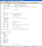
I currently program with Mplab IDE assembly below is a sample of what its like.
To some folk is easy and sensible, for others it baffling - everyones different.
 

Attachments

  • ScreenShot005.jpg
    ScreenShot005.jpg
    103.8 KB · Views: 99
I posted the C because that was the only language I was familiar with :p
Like I said, I know very little about MCU's and assembly code, that's why I chose FlowCode. Your code looks much MUCH simpler than what FlowCode spit out :p
Here's the ASM it gave me:
Code:
;/////////////////////////////////////////////////////////////////////////////////
;// Code Generator: BoostC Compiler - http://www.sourceboost.com
;// Version       : 7.03
;// License Type  : Lite License (Unregistered)
;// Limitations   : PIC12,PIC16 max code size:2048 words, max RAM banks:2, Non commercial use only
;/////////////////////////////////////////////////////////////////////////////////

	include "P16F628A.inc"
; Heap block 0, size:95 (0x000000A0 - 0x000000FE)
__HEAP_BLOCK0_BANK               EQU	0x00000001
__HEAP_BLOCK0_START_OFFSET       EQU	0x00000020
__HEAP_BLOCK0_END_OFFSET         EQU	0x0000007E
; Heap block 1, size:43 (0x00000045 - 0x0000006F)
__HEAP_BLOCK1_BANK               EQU	0x00000000
__HEAP_BLOCK1_START_OFFSET       EQU	0x00000045
__HEAP_BLOCK1_END_OFFSET         EQU	0x0000006F
; Heap block 2, size:0 (0x00000000 - 0x00000000)
__HEAP_BLOCK2_BANK               EQU	0x00000000
__HEAP_BLOCK2_START_OFFSET       EQU	0x00000000
__HEAP_BLOCK2_END_OFFSET         EQU	0x00000000
; Heap block 3, size:0 (0x00000000 - 0x00000000)
__HEAP_BLOCK3_BANK               EQU	0x00000000
__HEAP_BLOCK3_START_OFFSET       EQU	0x00000000
__HEAP_BLOCK3_END_OFFSET         EQU	0x00000000
gbl_status                       EQU	0x00000003 ; bytes:1
gbl_16_LSR                       EQU	0x00000020 ; bytes:4
gbl_float_detect_tininess        EQU	0x00000039 ; bytes:1
gbl_float_rounding_mode          EQU	0x0000003A ; bytes:1
gbl_float_exception_flags        EQU	0x0000003B ; bytes:1
gbl_17_gbl_aSig                  EQU	0x00000024 ; bytes:4
gbl_17_gbl_bSig                  EQU	0x00000028 ; bytes:4
gbl_17_gbl_zSig                  EQU	0x0000002C ; bytes:4
gbl_17_gbl_aExp                  EQU	0x0000003C ; bytes:1
gbl_17_gbl_bExp                  EQU	0x0000003D ; bytes:1
gbl_17_gbl_zExp                  EQU	0x00000037 ; bytes:2
gbl_17_gbl_aSign                 EQU	0x0000003E ; bytes:1
gbl_17_gbl_bSign                 EQU	0x0000003F ; bytes:1
gbl_17_gbl_zSign                 EQU	0x00000040 ; bytes:1
gbl_17_gbl_zSigZero              EQU	0x00000041 ; bytes:1
gbl_17_gbl_ret                   EQU	0x00000030 ; bytes:4
gbl_indf                         EQU	0x00000000 ; bytes:1
gbl_tmr0                         EQU	0x00000001 ; bytes:1
gbl_pcl                          EQU	0x00000002 ; bytes:1
gbl_fsr                          EQU	0x00000004 ; bytes:1
gbl_porta                        EQU	0x00000005 ; bytes:1
gbl_portb                        EQU	0x00000006 ; bytes:1
gbl_pclath                       EQU	0x0000000A ; bytes:1
gbl_intcon                       EQU	0x0000000B ; bytes:1
gbl_pir1                         EQU	0x0000000C ; bytes:1
gbl_tmr1l                        EQU	0x0000000E ; bytes:1
gbl_tmr1h                        EQU	0x0000000F ; bytes:1
gbl_t1con                        EQU	0x00000010 ; bytes:1
gbl_tmr2                         EQU	0x00000011 ; bytes:1
gbl_t2con                        EQU	0x00000012 ; bytes:1
gbl_ccpr1l                       EQU	0x00000015 ; bytes:1
gbl_ccpr1h                       EQU	0x00000016 ; bytes:1
gbl_ccp1con                      EQU	0x00000017 ; bytes:1
gbl_rcsta                        EQU	0x00000018 ; bytes:1
gbl_txreg                        EQU	0x00000019 ; bytes:1
gbl_rcreg                        EQU	0x0000001A ; bytes:1
gbl_cmcon                        EQU	0x0000001F ; bytes:1
gbl_option_reg                   EQU	0x00000081 ; bytes:1
gbl_trisa                        EQU	0x00000085 ; bytes:1
gbl_trisb                        EQU	0x00000086 ; bytes:1
gbl_pie1                         EQU	0x0000008C ; bytes:1
gbl_pcon                         EQU	0x0000008E ; bytes:1
gbl_pr2                          EQU	0x00000092 ; bytes:1
gbl_txsta                        EQU	0x00000098 ; bytes:1
gbl_spbrg                        EQU	0x00000099 ; bytes:1
gbl_eedata                       EQU	0x0000009A ; bytes:1
gbl_eeadr                        EQU	0x0000009B ; bytes:1
gbl_eecon1                       EQU	0x0000009C ; bytes:1
gbl_eecon2                       EQU	0x0000009D ; bytes:1
gbl_vrcon                        EQU	0x0000009F ; bytes:1
gbl_FCV_IGN                      EQU	0x00000042 ; bytes:1
CompTempVar2201                  EQU	0x00000043 ; bytes:1
CompTempVar2203                  EQU	0x00000043 ; bytes:1
CompTempVar2204                  EQU	0x00000043 ; bytes:1
CompTempVar2206                  EQU	0x00000043 ; bytes:1
CompTempVar2207                  EQU	0x00000043 ; bytes:1
CompTempVar2208                  EQU	0x00000044 ; bytes:1
delay_ms_00000_arg_del           EQU	0x00000044 ; bytes:1
delay_s_00000_arg_del            EQU	0x00000043 ; bytes:1
Int1Context                      EQU	0x0000007F ; bytes:1
Int1BContext                     EQU	0x00000034 ; bytes:3
	ORG 0x00000000
	GOTO	_startup
	ORG 0x00000004
	MOVWF Int1Context
	SWAPF STATUS, W
	BCF STATUS, RP0
	BCF STATUS, RP1
	MOVWF Int1BContext
	SWAPF PCLATH, W
	MOVWF Int1BContext+D'1'
	SWAPF FSR, W
	MOVWF Int1BContext+D'2'
	BCF PCLATH,3
	BCF PCLATH,4
	GOTO	interrupt
	ORG 0x00000010
delay_ms_00000
; { delay_ms ; function begin
	MOVF delay_ms_00000_arg_del, F
	BTFSS STATUS,Z
	GOTO	label1
	RETURN
label1
	MOVLW 0xF5
label2
	NOP
	NOP
	NOP
	NOP
	NOP
	NOP
	NOP
	NOP
	NOP
	NOP
	NOP
	NOP
	NOP
	NOP
	NOP
	NOP
	ADDLW 0xFF
	BTFSS STATUS,Z
	GOTO	label2
	NOP
	NOP
	NOP
	NOP
	NOP
	NOP
	NOP
	NOP
	NOP
	NOP
	NOP
	NOP
	NOP
	DECFSZ delay_ms_00000_arg_del, F
	GOTO	label1
	RETURN
; } delay_ms function end

	ORG 0x00000038
delay_s_00000
; { delay_s ; function begin
label3
	MOVLW 0xFA
	MOVWF delay_ms_00000_arg_del
	CALL delay_ms_00000
	MOVLW 0xFA
	MOVWF delay_ms_00000_arg_del
	CALL delay_ms_00000
	MOVLW 0xFA
	MOVWF delay_ms_00000_arg_del
	CALL delay_ms_00000
	MOVLW 0xFA
	MOVWF delay_ms_00000_arg_del
	CALL delay_ms_00000
	DECFSZ delay_s_00000_arg_del, F
	GOTO	label3
	RETURN
; } delay_s function end

	ORG 0x00000047
FCM_Power__00047
; { FCM_Power_Off ; function begin
	MOVLW 0xFF
	BCF STATUS, RP0
	BCF STATUS, RP1
	MOVWF delay_s_00000_arg_del
	CALL delay_s_00000
	MOVLW 0x2D
	MOVWF delay_s_00000_arg_del
	CALL delay_s_00000
	MOVLW 0x01
	BSF STATUS, RP0
	IORWF gbl_trisb, W
	MOVWF gbl_trisb
	MOVLW 0x01
	BCF STATUS, RP0
	ANDWF gbl_portb, W
	MOVWF CompTempVar2201
	CLRF gbl_FCV_IGN
	DECF CompTempVar2201, W
	BTFSC STATUS,Z
	INCF gbl_FCV_IGN, F
	MOVF gbl_FCV_IGN, F
	BTFSS STATUS,Z
	RETURN
	MOVLW 0xFB
	BSF STATUS, RP0
	ANDWF gbl_trisb, W
	MOVWF gbl_trisb
	MOVLW 0xFB
	BCF STATUS, RP0
	ANDWF gbl_portb, W
	MOVWF CompTempVar2203
	MOVLW 0x04
	IORWF CompTempVar2203, W
	MOVWF gbl_portb
	MOVLW 0x78
	MOVWF delay_s_00000_arg_del
	CALL delay_s_00000
	MOVLW 0xFD
	BSF STATUS, RP0
	ANDWF gbl_trisb, W
	MOVWF gbl_trisb
	MOVLW 0xFD
	BCF STATUS, RP0
	ANDWF gbl_portb, W
	MOVWF gbl_portb
	MOVLW 0xFB
	BSF STATUS, RP0
	ANDWF gbl_trisb, W
	MOVWF gbl_trisb
	MOVLW 0xFB
	BCF STATUS, RP0
	ANDWF gbl_portb, W
	MOVWF gbl_portb
	RETURN
; } FCM_Power_Off function end

	ORG 0x0000007D
main
; { main ; function begin
	MOVLW 0x07
	BCF STATUS, RP0
	BCF STATUS, RP1
	MOVWF gbl_cmcon
	MOVLW 0xC0
	BSF STATUS, RP0
	MOVWF gbl_option_reg
label4
	MOVLW 0xFB
	BSF STATUS, RP0
	ANDWF gbl_trisb, W
	MOVWF gbl_trisb
	MOVLW 0xFB
	BCF STATUS, RP0
	ANDWF gbl_portb, W
	MOVWF gbl_portb
	MOVLW 0x01
	BSF STATUS, RP0
	IORWF gbl_trisb, W
	MOVWF gbl_trisb
	MOVLW 0x01
	BCF STATUS, RP0
	ANDWF gbl_portb, W
	MOVWF CompTempVar2204
	CLRF gbl_FCV_IGN
	DECF CompTempVar2204, W
	BTFSC STATUS,Z
	INCF gbl_FCV_IGN, F
	DECF gbl_FCV_IGN, W
	BTFSS STATUS,Z
	GOTO	label4
	MOVLW 0xFD
	BSF STATUS, RP0
	ANDWF gbl_trisb, W
	MOVWF gbl_trisb
	MOVLW 0xFD
	BCF STATUS, RP0
	ANDWF gbl_portb, W
	MOVWF CompTempVar2206
	MOVLW 0x02
	IORWF CompTempVar2206, W
	MOVWF gbl_portb
label5
	MOVLW 0x01
	BSF STATUS, RP0
	IORWF gbl_trisb, W
	MOVWF gbl_trisb
	MOVLW 0x01
	BCF STATUS, RP0
	ANDWF gbl_portb, W
	MOVWF CompTempVar2207
	CLRF CompTempVar2208
	DECF CompTempVar2207, W
	BTFSC STATUS,Z
	INCF CompTempVar2208, F
	MOVF CompTempVar2208, W
	MOVWF gbl_FCV_IGN
	MOVF gbl_FCV_IGN, F
	BTFSS STATUS,Z
	GOTO	label5
	CALL FCM_Power__00047
	GOTO	label4
; } main function end

	ORG 0x000000B9
_startup
	MOVLW 0xD5
	BCF STATUS, RP0
	BCF STATUS, RP1
	MOVWF gbl_16_LSR
	MOVLW 0xC4
	MOVWF gbl_16_LSR+D'1'
	MOVLW 0xBB
	MOVWF gbl_16_LSR+D'2'
	MOVLW 0xDC
	MOVWF gbl_16_LSR+D'3'
	CLRF gbl_17_gbl_aSig
	CLRF gbl_17_gbl_aSig+D'1'
	CLRF gbl_17_gbl_aSig+D'2'
	CLRF gbl_17_gbl_aSig+D'3'
	CLRF gbl_17_gbl_bSig
	CLRF gbl_17_gbl_bSig+D'1'
	CLRF gbl_17_gbl_bSig+D'2'
	CLRF gbl_17_gbl_bSig+D'3'
	CLRF gbl_17_gbl_zSig
	CLRF gbl_17_gbl_zSig+D'1'
	CLRF gbl_17_gbl_zSig+D'2'
	CLRF gbl_17_gbl_zSig+D'3'
	CLRF gbl_17_gbl_aExp
	CLRF gbl_17_gbl_bExp
	CLRF gbl_17_gbl_zExp
	CLRF gbl_17_gbl_zExp+D'1'
	CLRF gbl_17_gbl_aSign
	CLRF gbl_17_gbl_bSign
	CLRF gbl_17_gbl_zSign
	CLRF gbl_17_gbl_zSigZero
	CLRF gbl_17_gbl_ret
	CLRF gbl_17_gbl_ret+D'1'
	CLRF gbl_17_gbl_ret+D'2'
	CLRF gbl_17_gbl_ret+D'3'
	CLRF gbl_float_rounding_mode
	CLRF gbl_float_exception_flags
	CLRF gbl_float_detect_tininess
	BCF PCLATH,3
	BCF PCLATH,4
	GOTO	main
	ORG 0x000000E1
interrupt
; { interrupt ; function begin
	BCF STATUS, RP0
	BCF STATUS, RP1
	SWAPF Int1BContext+D'2', W
	MOVWF FSR
	SWAPF Int1BContext+D'1', W
	MOVWF PCLATH
	SWAPF Int1BContext, W
	MOVWF STATUS
	SWAPF Int1Context, F
	SWAPF Int1Context, W
	RETFIE
; } interrupt function end

	END

Do you know if that would do the trick?

Also, I'm assuming that sending 1 to the output makes the pin go high?
 

Hi,

Think you can see that the Assembler version is just a bloated as the C listing - its very difficult to work though.

I assume the current free Flowcode does not have a simulator that alows you to 'run' the code and check the program function and i/o.

You could try posting your program .hex code and I could try running it in a simulator, you need to provide details of what ports are inputs and outputs.

Yes, a 1 or setting the output Pin High makes the pin go high and drive a relay on, via a transistor.
 

Status
Not open for further replies.

Similar threads

Part and Inventory Search

Welcome to EDABoard.com

Sponsor

Back
Top