Continue to Site

Welcome to EDAboard.com

Welcome to our site! EDAboard.com is an international Electronics Discussion Forum focused on EDA software, circuits, schematics, books, theory, papers, asic, pld, 8051, DSP, Network, RF, Analog Design, PCB, Service Manuals... and a whole lot more! To participate you need to register. Registration is free. Click here to register now.

Need help with digital switch circuit(BJT).

Status
Not open for further replies.

gvardan

Newbie level 6
Joined
Jun 15, 2010
Messages
13
Helped
0
Reputation
0
Reaction score
0
Trophy points
1,281
Location
Canada
Activity points
1,434
Hi,
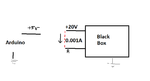
I am trying to make digital switch circuit for an old motor driver, that can be controlled by Arduino. Motor driver is pretty old and it's like a black box for me at this moment, but based on my tests I have put out the requirement on the picture attached.
Basically, arduino should close the circuit .

I tried the PNP BJT solution mentioned in this site **broken link removed**, however it does not seem to work.. I used a MPS2907A transistor that I found.

I would really appreciate some help or any other suggestions.
 

Attachments

  • Circuit.png
    Circuit.png
    8.4 KB · Views: 67

Use this circuit instead
(relay driver)
https://pradhap87.blogspot.com.ar/2010/01/relay-lockun-lock-unit.html
just replace the relay coil with the motor.

The circuit that you are using (figure 1) is going to be always ON unless the input voltage is near the supply voltage.
The arduino delivers +5volts at the most. So the arduino will not be able to turn it OFF. Unless you use an open collector output.
Fig 2 is ok but add the diode in parallel with the motor that is included in my link, to protect the transistor.

Hope that this helps

Hey thanks for the response,
It explains the behavior I was observing, however I'm not sure how to use Figure 2 in my case. As you can see from my attachment, it does not really have a load. I just want to short circuit +20V and input A. This is an enable signal that is going to the motor driver (black box)...
 

I assumed that the motor is small with low current requirements. If not you should use other transistors.
The relay driver in my first link is essentially the same as the one on fig 2 of your link.
The motor is connected between the +20v supply and the collector of the 2n2222. A diode is placed in parallel with the motor and should be reversed bias (no conduction) as shown in the link, otherwise it will blow the transistor.
The transistor acts as a switch to ground to turn the motor on.

If the driver of the motor is already in the black box to send 20v you can use the circuit on fig2 between the arduino and your original circuit. With +5v the 2n2222 will place 0v on the input of the PNP transistor turning it on. With 0v the 2N2222 will be off and the PNP transistor will be off.
 
Last edited:

Status
Not open for further replies.

Similar threads

Part and Inventory Search

Welcome to EDABoard.com

Sponsor

Back
Top