Matthew10_28
Newbie level 2
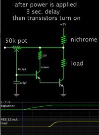
Right now, I have a 3V 1500mAh CR123 battery connected to a switch and a small length of nichrome wire. When it is switched on, the nichrome wire heats up until it breaks as it should. Naturally, the circuit is open at this point and it's served its purpose. From my understanding, it takes about .25 amps for about a second to heat the wire until it breaks.
I'd like to add a 3-5 second delay (user adjustable would be nice) to this, such that when the switch is turned on, nothing passes through the nichrome wire until the allotted time has passed. Then the nichrome would heat up and break as before, opening the circuit. Once the nichrome wire breaks, the device won't be interacted with for a long time, so having the battery continue to drain would be unnecessarily problematic. This has to be resettable (loaded with another nichrome wire). I've looked into using a 555 delay on circuit but I don't have a good understanding of how it really works. There seems like a lot of variations to it as well. I've got a degree in mechanical engineering, but I just can't wrap my head around how to design this. Any help would be appreciated.
I'd like to add a 3-5 second delay (user adjustable would be nice) to this, such that when the switch is turned on, nothing passes through the nichrome wire until the allotted time has passed. Then the nichrome would heat up and break as before, opening the circuit. Once the nichrome wire breaks, the device won't be interacted with for a long time, so having the battery continue to drain would be unnecessarily problematic. This has to be resettable (loaded with another nichrome wire). I've looked into using a 555 delay on circuit but I don't have a good understanding of how it really works. There seems like a lot of variations to it as well. I've got a degree in mechanical engineering, but I just can't wrap my head around how to design this. Any help would be appreciated.
