Continue to Site

Welcome to EDAboard.com

Welcome to our site! EDAboard.com is an international Electronics Discussion Forum focused on EDA software, circuits, schematics, books, theory, papers, asic, pld, 8051, DSP, Network, RF, Analog Design, PCB, Service Manuals... and a whole lot more! To participate you need to register. Registration is free. Click here to register now.

Need help with a radio transmitter 27 MHz - AM

Status
Not open for further replies.

Victor Petrescu

Newbie level 2
Joined
Jan 15, 2015
Messages
2
Helped
0
Reputation
0
Reaction score
0
Trophy points
1
Activity points
17
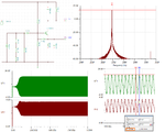
Hello I have a request if anyone can help me with some answers about this project. I did a radio transmitter in 27 MHz with modulation AM ... and I have problems in maintaining oscillations and I think it is because quartz oscillator. And a second question do not understand why the current from the entry of the third transistor so I have a little ... and so I suspect that the transistor does not open as a resut i don't have enough gain. I would like if anyone can help me fix the problem. I attached 2 photos with the wiring diagram and simulation result. i used to simulate PSPICE .


rezultat simulare emitator 27 Mhz - MA.jpg


schema electrica emitator 27 Mhz - MA.jpg


Thank you very much!
 

Some Spice simulators have problems to start an oscillation when using a crystal model, or the equivalent circuit of a crystal.
Replace the entire equivalent crystal circuit with a simple shunt LC circuit (1uH and 33pF, and keep C9 in place) and you will get the 27MHz oscillation, just to see how the rest of the circuit works.
 

I've done what you said and i obtained this

rezultat.jpg

My concern is that i have quite a lot of amplification, but i'm thinking is because of the soft
 
Last edited:

The "amplification" is most likely provided by the output LC filter without an effective load.

The screenshot schematic is hard to read, I can't recognize the modulation source settings. Similarly the waveform doesn't give much information with the presently selected time scale.
 

You intend to AM but you're using C-Class amplifier for that..It's wrong because C-Class amplifiers need relatively high input driving levels.
You have to use A-Class amplifier to amplify the modulated signal.Simulators can sometimes not provide start-up conditions for oscillators as you can see that your oscilaltion is damped and it is dying down.( I guess the oscillator is heavily loaded by the amplifier).
Thake these points into account..
 

I reworked the bias values and relaxed the Q of the crystal equivalent circuit a bit. After that the circuit simulated quite quickly and reached a steady state under 250 uS. I agree with BigBoss that you need some buffer stage to prevent loading on the LC tank circuit.
 

Attachments

  • 27M_osc.png
    27M_osc.png
    66.3 KB · Views: 64

Status
Not open for further replies.

Part and Inventory Search

Welcome to EDABoard.com

Sponsor

Back
Top