keystoneclimber
Newbie level 3
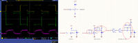
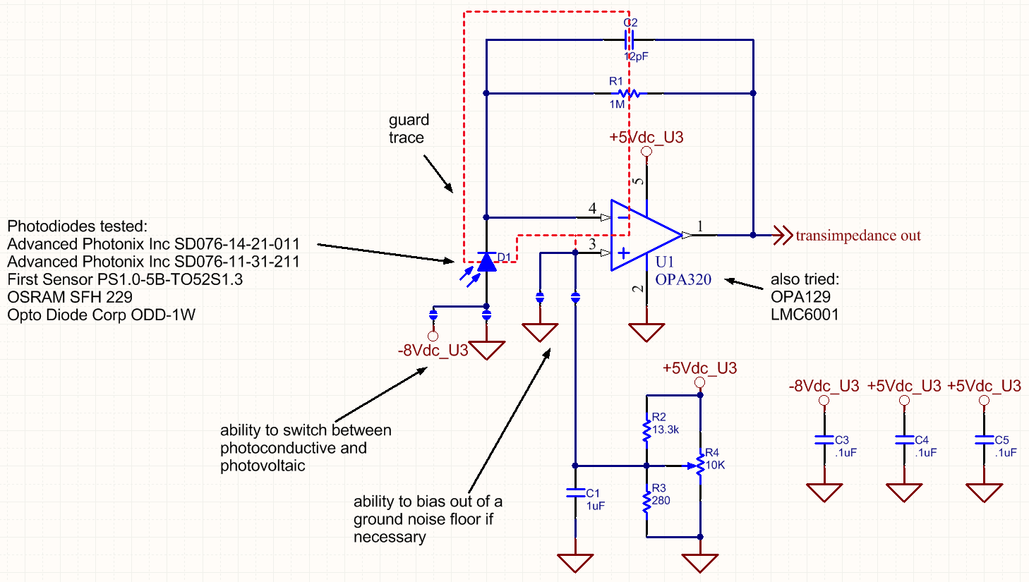
I'm trying to drive an LED with a square wave / pulses and look at the output with a photodiode / transimpedance amp detector. The starting frequency is about 1 KHz but I will eventually go up to about 100 Khz. The problem I'm running into is non-square LED output waveforms being sensed by the detector. In the scope capture, channel 1 is the driving waveform, channel 4 is the signal at the LED and channel 3 is the detector output. My first thought was to try a different LED driver circuit, specifically a shunt driver configuration. I read online that adding some RC components could speed it up (increase the slew rate). I found on another site something similar albeit a digital driver that uses dual inverters as drivers. Could someone explain to me what these RC networks are doing (specifically) and how to determine the appropriate values for them? Thanks in advance.