Continue to Site

Welcome to EDAboard.com

Welcome to our site! EDAboard.com is an international Electronics Discussion Forum focused on EDA software, circuits, schematics, books, theory, papers, asic, pld, 8051, DSP, Network, RF, Analog Design, PCB, Service Manuals... and a whole lot more! To participate you need to register. Registration is free. Click here to register now.

Need help understanding fast LED driver.

Status
Not open for further replies.

keystoneclimber

Newbie level 3
Joined
Nov 13, 2007
Messages
3
Helped
0
Reputation
0
Reaction score
0
Trophy points
1,281
Activity points
1,345
I'm trying to drive an LED with a square wave / pulses and look at the output with a photodiode / transimpedance amp detector. The starting frequency is about 1 KHz but I will eventually go up to about 100 Khz. The problem I'm running into is non-square LED output waveforms being sensed by the detector. In the scope capture, channel 1 is the driving waveform, channel 4 is the signal at the LED and channel 3 is the detector output. My first thought was to try a different LED driver circuit, specifically a shunt driver configuration. I read online that adding some RC components could speed it up (increase the slew rate). I found on another site something similar albeit a digital driver that uses dual inverters as drivers. Could someone explain to me what these RC networks are doing (specifically) and how to determine the appropriate values for them? Thanks in advance.


Going back to your basic circuit theory, a capacitor is essentially a short circuit when voltage is first applied to it. As the charge builds up, the current drops. The same thing happens here: when you first apply your square wave, the base resistor is bypassed, driving a large current into the base; after a time, the cap charges, and current flows only through the resistor.
 

Hi,

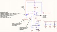
In my eyes the soft edge is not caused by the LED driver, but by the photodiode circuit.

Klaus
 

Yes, the LED drive waveform is fine.
It's the detector circuit that needs improvement.
Please post the schematic of that.


While my slew problem may very well be with the detector rather the emitter, my original question still stands... Can anyone explain (in detail) the function of the RC networks circled above in speeding up the driver circuit and how to pick values based on operating frequency?
 

Your received waveform shows the 12 µs low-pass time constant you have built into the transimpedance amplifier. C2 and/or R1 should be decreased.
 
Capacitive current spikes will not improve slew rate as much as using a lower driving impedance would ( voltage source) The received signal shows a small step voltage from integrating the spike current.

Since LED's have capacitance at 0V the slew rate depends on the Vol source impedance when using a high side driver with open collector or Totem Pole TTL.

To improve slew rate, you must drive it at the ESR impedance of the LED or lower.
A 65mW LED is between 15 and 20 Ohms ESR
A 0.5W LED is between 1 to 2 Ohms
A 3W LED is around 1/3 Ohm

Thus you need a complementary driver like CMOS with 3V to a white LED or with 5V logic with a small Series resistance to limit current. ALV type CMOS is 25 to 50 Ohms ESR output impedance depending on family , calculating Vol/Iol. Using devices in parallel will reduce the source impedance and drive current so a series R is chosen with ESR of LED and supply voltage. The supply voltage could be used to regulate the current with care or add a small Rs to limit current.

There are other factors which limit the slew rate in LED's beside source impedance and diode capacitance, so high slew rate is a challenge. As ESR drops with rising power, so too diode capacitance increases so this Figure of Merit as the C*ESR product is never spec'd , it varies with different OEM's designs and chip performance.

Low driver inductance is also needed , so keep leads short and avoid loops.

IR LED's tend to be faster and are used in high speed communication like IRDA2. >1Mhz
Look for IRDA 2 drivers , transmitters, receivers and Rx/TX chips.

Remote control IR LED's can be pulsed with 1A at 1.5V but the us size pulses are just run at a carrier frequency between 25~60kHZ then the burst is modulated for data.
 
Status
Not open for further replies.

Similar threads

Part and Inventory Search

Welcome to EDABoard.com

Sponsor

Back
Top