Welcome to our site! EDAboard.com is an international Electronics Discussion Forum focused on EDA software, circuits, schematics, books, theory, papers, asic, pld, 8051, DSP, Network, RF, Analog Design, PCB, Service Manuals... and a whole lot more! To participate you need to register. Registration is free. Click here to register now.
Hi Swild
if the TL characteristic impedance is 50, the ratio is 1:1.
Rgds
---------- Post added at 15:25 ---------- Previous post was at 15:17 ----------
I think this is relevant, what is the ratio if the TL impedance Z0 is 25 Ohms? I see a lot of situations of this kind in my everyday work, and the length of TL is normally 1/8 wave length.
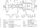
As the schematic clarifies, the TL impedance is 50 ohm.
Apart from this point, it's unclear however, because it doesn't tell about the TL geometry. The coupling of both lines definitely matters, there may be possibly a core not shown in the schematic. From the schematic allone, it can't be determined, if the structure is operating as a resonant (λ/4 or whatever) transmission line transformer or a wideband balun.
to Swild: Thanks, if the length is λ/4, your answer is right, what I really want to know is the wide-band case, which often shows itself as a λ/8 cable (at mid-band)
to FvM: if TL impedance is 50, than the length is irrelevant, the ratio will always be 1:1. As to the coupling effect you mentioned, I think the other cable is used here only to balance the (supposed) balanced port of transformer, and there is no signal at that cable, so in the first order, no coupling will be detected.
This site uses cookies to help personalise content, tailor your experience and to keep you logged in if you register.
By continuing to use this site, you are consenting to our use of cookies.