Continue to Site

Welcome to EDAboard.com

Welcome to our site! EDAboard.com is an international Electronics Discussion Forum focused on EDA software, circuits, schematics, books, theory, papers, asic, pld, 8051, DSP, Network, RF, Analog Design, PCB, Service Manuals... and a whole lot more! To participate you need to register. Registration is free. Click here to register now.

Need help on one-time trigger switch...

Status
Not open for further replies.

rajesh101

Newbie level 3
Joined
Apr 29, 2011
Messages
4
Helped
0
Reputation
0
Reaction score
0
Trophy points
1,281
Activity points
1,303
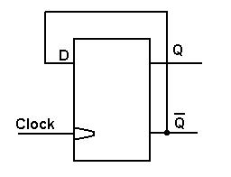
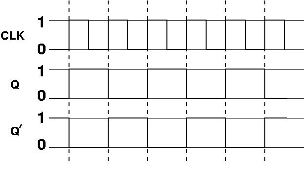
I am designing an RF circuit that needs a one time trigger switch i.e. it should put on the circuit if a positive voltage pulse is given once and should turn it off if another pulse is sent to it. Are there any trigger-type switch available for that?
Thanks in advance...
 

Sounds like you're talking about a simple RS flip flop. A memory circuit built around two transistors and a few resistors.

Two inputs R (for reset) and S (for set). Outputs are called Q and NOT Q.

Grounding an input lead turns off a transistor and turns on the other transistor. It holds this state indefinitely. You can return the input lead to positive and the circuit won't change state. Thus it has a memory.

When you ground the other lead, the circuit switches to the opposite state. And holds it indefinitely.

You pick up the HI-LO output at the transistor collectors.

RS flipflops are available in common IC chips, or you can build it with transistors.
 
Last edited:

I actually thought about the RS flip flop too but the thing is we will have only positive pulse to be given at a port and hence it should be able to turn the circuit on if a first +ve pulse is given and turn it on if another +ve pulse is given...i mean the positive pulse is not continuous....:-?
 

Guess you could say that was my generic description of an RS flip flop.

I neglected to mention...

It can be made to do what you're asking. Just use PNP transistors and flip the circuit head for heel.

You change state by applying a positive pulse to the inputs. The input signal can continue positive or go to high impedance. But not to ground.

My first description above (for NPN construction) was in error by saying input can go to positive.

And (re PNP type flop flop) you must avoid applying positive to both inputs simultaneously.
 
Last edited:

Hi
you can do that by configuring D Flip-flop as toggle Flip-flop
Below is shown a D type flip-flop connected as a toggle type.

On each clock pulse positive going edge, Q will go to the state bar Q was before the clock pulse arrived.
Therefore Q will toggle.

You can use IC CD4013 D-flip flop to do that.

Hope this helps...
 

Re-reading the above posts I realize I might have got the wrong idea that your ON signal comes from one source and the OFF signal from a different source. A flip flop would be suitable for that since it has two separate inputs.

However now I realize you were probably talking about the pulses coming down the same wire.

In that case you need a pulse-ON-pulse-OFF type of circuit. (Also known as a divide-by-two counter). Therefore vinoth8051 is correct.
 

Status
Not open for further replies.

Similar threads

Part and Inventory Search

Welcome to EDABoard.com

Sponsor

Back
Top