Continue to Site

Welcome to EDAboard.com

Welcome to our site! EDAboard.com is an international Electronics Discussion Forum focused on EDA software, circuits, schematics, books, theory, papers, asic, pld, 8051, DSP, Network, RF, Analog Design, PCB, Service Manuals... and a whole lot more! To participate you need to register. Registration is free. Click here to register now.

Need help for low current circuit with capacitor driving LED

Status
Not open for further replies.

BearOfThunder

Newbie level 5
Joined
Dec 13, 2021
Messages
8
Helped
0
Reputation
0
Reaction score
0
Trophy points
1
Activity points
233
I am new to electronics, so I come here for some help to understand what to do.

I have a practical problem so let me just explain what i have and what i am trying achieve.

I am an artist and i make sculptures. I use wireless power transfer to light up LEDs inside my sculptures.
Here is a link to the electronics I am using: https://www.aliexpress.com/item/32944450041.html?spm=a2g0s.9042311.0.0.27424c4d4nsB8n

The nice thing about this solution is that the sculpture, which is meant to be held and handeled, lights up when it is put back on it's plinth.

I would like to add an extra feature to the scultures, and that is to have the light inside the sculpture hold it's light for some time after it is removed from it's plinth. Like the plinth charges it up like a power station, and when the sculture is removed it holds a slowly fading light for between 10 seconds or more. I feel like this would create another element of "magic" to my sculptures.

What I have tried so far is to buy a 6F 2.7v (super-)capacitor. Maybe this is totally wrong capacitor, i have no idea. I have played around with it, but I can't find any way to charge the capacitor with the wireless power from the transmitter. The charging have to happen through the recieving coil inside the sculpture.

I know the capacitor is working because i can charge it up by touching it to a 9V batteri for half a second. I know the voltage of the battery is wrong, but half a second of contact does not seem to harm the capacitor. With this short touch the capacitor can light up one LED (1W) for about 10 minutes....slowly fading all the time. 10 minutes are more than i need, so I really don't know what capacitor to use.

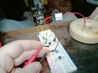
If you follow the link above to the transmitter and receivers I am using, you will see that the transmitting coil is about 75mm in diameter, while the receiving coils are only 14.5mm in diameter. The transmitter can give up to 700mA, and can light up many receivers, but for relatively bright light about 3 receivers seem to be the limit. I use only one or two in my sculptures.

I use 1W LEDs rated to use about 300mA when bright, but the LED light up at far lower input, and that is ok if it is just bright enough.
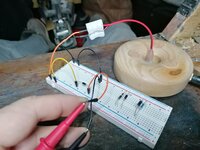
I have tried to measure the Voltage in the recieving coil and get about 80-120mV reading. I am not sure if this reading is accurate, but the LED lights up quite well anyways. There seems to be a tiny diode or capacitor connected to the receiving coil, but the funny thing is that the LEDs does not care what is plus and what is minus, they light up in any direction. I can't say that this is puzzling to me, since i don't really know what happens here, but it does not seem to fit with what i read different places about LEDs. The brightness of the LED is of course dependent on the position in relation to the transmitter...max seems to be about 4 cm over the transmitter in the center and on the same plane.

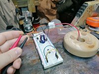
As stated before I can't get any charge into the capacitor I have with this low current from a recieving coil, so I probably need a different capacitor, but maybe also other components to make this work. What I have noticed is that if i connect this capacitor in parallell with the LED (receiving coil, capacitor and LED in parallell and put the receiver in the transmitter), then the LED will not light up at all, and no charge I can use seems to have built up in the capacitor while i do this.

That is all information i can think of at this point, please ask if you need details to help me with this.

Can anyone help me get this to work the way I want it?
 

Thanks for your reply.

Ok, well... so I obviously have the wrong capacitor. But how can I use the receivers I have mentioned to charge a li-ion battery?

It is not an option to require the owner to swap batteries in the sculpture. Either battery or capacitor must be charged with the receiver integrated in the statue, or else this idea will not work as required.

The lighting inside will eventually need maintainance, but it should be years between such maintainance procedures. I also don't want the LED to be glowing very long, just a delay for 10 seconds or up to a minute after the sculpture leaves the plinth.
 

I think what Easy Peasy is suggesting is that you use a rechargeable battery rather than a capacitor. Assuming the sculpture will be on its plinth for most of the time, the battery can be trickle charged and should power the LED for several hours when lifted. The operational difference between a battery and capacitor is that a battery converts stored energy using a chemical process and reproduces it when being discharged, a capacitor also stores energy but it cannot produce it so the voltage decays from the instant you start to draw from it.

Wireless transfer uses AC, it is a fundamental property of electromagnetic energy transfer that only a change in magnetic field as opposed to a static level of magnetism can result in power recovery at the 'receiving' side. By using AC the field is constantly changing so you get reasonably good transfer. The problem you have is that batteries and capacitors and LEDs need DC to operate. So what you have to do is rectify the AC with a diode (or more than one for better efficiency) so the polarity can't alternate, then store it afterwards.

A little extra circuitry is therefore required. A single diode to 'convert' AC to DC will work but only half the available power can be harvested. A diode bridge (four diodes) will recover more from the AC. The drawback is that each diode also drops the voltage a little, a single diode will drop about 0.7V and a bridge configuration will drop about 1.4V, which works out best to use will depend on whether you can afford to lost that extra voltage or not.

The diodes will have to be 'fast' devices, normal power rectifiers will not work. They are not expensive or hard to find. Incidentally, you are very lucky not to have permanently damaged your capacitor. I would guess some damage has occurred already but it still partially functions.

Brian.
 

Thank you for a very informative answer. :)

I understand from you answer that I can be totally sure that the transmitter are sending AC current because this is the only way it can happen wirelessly. This means that none of the readings I have done before with my multimeter are correct, because I have been trying to measure the wrong thing from the receiver, This explains why I could not get any consistent readings.

Now that I know what to measure I get consistent readings:

Voltage:
- In the center of the transmitter coil: 2.0 - 2.2 V (peaks up to 2.6V when the reveiver is moving in and out of the field)
- outside of the transmitter close to the edge: 1.8 - 2.0V

Ampere:
- In the center of the transmitter on the same plane: 22mA
- Also in the center but elevated to where the receiver will most likely be: 3-7mA
- On the outer edge of the transmitter the amps are very low, allthough enough to make LEDs light up, but this is not important because the receiver will not usually be there.

Next I think I need to understand what is happening with the receiver. It is quite simple...just a coil with a LED soldered on it, but there is another component in between that I don't know what it is. I need to know what this is before I can think about converting the current.

Here is a picture of the reveiver I am working with:

IMG_20211214_080421c.jpg


The red circle shows the component I don't know what it is. Is it a diode or a tiny capacitor?
Is it possible to tell from the picture? What does it do in the circuit?

Thanks again for your answers, I hope you can help me along further in this...
 

You are understanding correctly.
The component circled in red is a ceramic capacitor. Its purpose is to 'tune' the pick-up coil to resonance. The concept isn't easy to understand but basically, just like a radio station is stronger when you accurately tune to it, the coil in the picture picks up most signal when it is tuned to the transmitting coil. It will still work without it but be less efficient.

To modify it, the simplest way is to disconnect one of the wires to the LED and add a diode, storage capacitor or battery and a resistor.

The diode converts the AC to DC (at the moment the LED only uses one half of the AC waveform anyway), the capacitor or battery stored the DC and the resistor limits how fast the current can flow through the LED. While it might seem counter-intuitive to limit the LED current, if you don't, the LED will sink all the current as it is produced and there will not be any left over to store.

20211214_084305a.jpg


Sorry about the poor sketch!
The coil and 'C' are the existing ones and the LED (the diode symbol with the arrows) is the same one. The new diode should ideally be a Schottky type, I would suggest a 1N5819 and 'R' will have to be found by experimentation but I would start with 100 Ohms. The other capacitor can be your super-capacitor or a rechargeable battery.

The unknown factor here is how much power is being transferred and there is no way to measure it without lab equipment. Note that because initially most of the power will go into charging the storage capacitor/battery, there will be a short delay before the LED lights up but it should stay lit for longer when the sculpture is lifted.

Brian.
 

There was once upon a time, a LED flasher special
purpose chip that would boost a low voltage (single AA)
to a pulse that could drive a red LED. I believe the
LM3909 has been obsoleted for a long time but
some folks have reverse engineered it to a practical
discrete-transistor lash-up. The flashing mode can
be set to a frequency high enough that it appears
constant.

You might like to decide whether embedding a
large capacity primary (or rechargable) Li cell can
give you a run time exceeding the time-on-display.
1AH @ 3.7V, if you ran the LEDs at 100mA total,
ought to get you through the day (or night);
maybe you just charge it after hours and put it
back in the object, as part of daily housekeeping.

Maybe you don't even need wireless charging;
what's wrong with a keyed base and two regular
contacts? Or a divorced-core transformer like an
electric toothbrush (wireless, but not at distance).
You'd likely get better transfer efficiency in smaller
form factor, meaning higher voltage to charge a
battery. Some primary side current limiting and an
overcharging-tolerant Li-chemistry species might
allow a real simple (i.e. no charge controller) scheme.
 
Wow...this is great information. And thanks for the sketch :)

As i understand it, the sketch to the left is describing my photo, and the one to the right include what I need to add...

Good to know what the tiny ceramic capacitor is for, so I will keep it in the circuit.

So, since the LED can only use direct current it is only making use of part of the waveform that goes in the direction it needs, whilst blocking flow in the oppositie direction because it is a DIODE like other diodes, right?

Great explanation about the resistor, it is starting to make sense to me why my testing so far have not worked out. Good thing that I have already ordered a set of resistors from 0.5ohm up to 2000ohm. Then i can test a wide variation for what works best.

When it comes to choosing a diode you say "Shottky" is the best....ok.
Is this becaise it is a diode with low voltage drop?

I ordered this kit that contains the spesific type you suggested.
Then I also have options if i need a different one.
https://www.aliexpress.com/item/32633071171.html?spm=a2g0o.productlist.0.0.6c723e1dsk7J8c&algo_pvid=3a4f00c8-1bf3-46de-93d4-e11ad0a5c17b&algo_exp_id=3a4f00c8-1bf3-46de-93d4-e11ad0a5c17b-2&pdp_ext_f={"sku_id":"12000016563917366"}

I have also looked at a MB10F SMD Bridge Stack Rectifier, is that a good altnernative for using the whole waveform and minimize voltage drop?
https://www.aliexpress.com/item/4001094849305.html?spm=a2g0o.productlist.0.0.48dc4257R335dp&algo_pvid=840ce55d-6b82-4e81-9e8b-cf7c280c25eb&algo_exp_id=840ce55d-6b82-4e81-9e8b-cf7c280c25eb-0&pdp_ext_f={"sku_id":"10000014380305204"}

Or maybe this one:
https://www.aliexpress.com/item/400...9a-0&pdp_ext_f={"sku_id":"10000001853740972"}

Or maybe this 2W10 2A 1000V Diode Bridge Rectifier?
https://www.aliexpress.com/item/4001025278628.html?spm=a2g0o.detail.0.0.686571f8cn3ccc&gps-id=pcDetailCartBuyAlsoBuy&scm=1007.12908.232710.0&scm_id=1007.12908.232710.0&scm-url=1007.12908.232710.0&pvid=a612b8ff-c55b-4dad-9b37-e656b2bee1ac&_t=gps-id:pcDetailCartBuyAlsoBuy,scm-url:1007.12908.232710.0,pvid:a612b8ff-c55b-4dad-9b37-e656b2bee1ac,tpp_buckets:668#2846#8111#1996&&pdp_ext_f={"sceneId":"2908","sku_id":"10000013566120072"}

You also said that the super-capacitors i already have can be used in this circuit, so thankfully I have several of them i case the one I have tested with so far is somehow damaged. Is this capacitor a good choise, or would you have preferred a different one?

If I should also test with a battery would this one be a good choise?
https://www.aliexpress.com/item/4001033075981.html?spm=a2g0o.productlist.0.0.15a5457bhYGRAE&algo_pvid=f8c3de6b-1027-46da-a980-e13438319e96&algo_exp_id=f8c3de6b-1027-46da-a980-e13438319e96-0&pdp_ext_f={"sku_id":"10000013664196410"}


I am a little worried that the voltage of 3.7V may be too much for the LED...

Or maybe a tiny one like this:
https://www.aliexpress.com/item/33000678954.html?spm=a2g0o.productlist.0.0.67eb1bb5bGKtOu&algo_pvid=bfbd5621-bfd3-42f1-b2e0-1abb1695c88a&algo_exp_id=bfbd5621-bfd3-42f1-b2e0-1abb1695c88a-1&pdp_ext_f={"sku_id":"66976329072"}

Thanks again for being so helpful.. I feel quite encouraged at this point :)

Bjorn
 

You might like to decide whether embedding a
large capacity primary (or rechargable) Li cell can
give you a run time exceeding the time-on-display.
1AH @ 3.7V, if you ran the LEDs at 100mA total,
ought to get you through the day (or night);
maybe you just charge it after hours and put it
back in the object, as part of daily housekeeping.
Thanks for your suggestion, but in this case the wireless power is a requirement. The object containing the light must not be opened other than for maintainance after a few years. Maybe I can use your suggestion in other products, so thanks :)
 

The diode ratings are almost irrelevant, you only need maybe 20V PIV rating and 0.2A current rating so all of those would be well within their capabilities.

There are two reasons why Schotky is better than a normal silicon diode (most of the ones you listed are not Schottky types), firstly is the lower voltage drop which is an advantage but more importantly they can start and stop conducting very quickly. The signal being transferred through the coil will be at a relatively high frequency, possibly 1MHz or more and normal diodes will work poorly if at all at that rate. To explain without getting into quantum theory, when a diode changes from not conducting (the voltage is 'backwards') to a conductive state it takes a short time to recover and pass the current. The time is very short, usually less than 1/1000 of a second for normal diodes but that equates to a frequency of only 1,000 Hz. Your power transfer is probably 1000 times faster than that so a normal diode will not have time to recover before the voltage reverses again. A Schottky diode is many times faster and stores less charge so it will operate at much higher switching rates.

Regarding the LED, all LEDs are current driven, not voltage. They don't conduct at all if the voltage across them is too low but at a certain threshold point they start to sink current and light up. The problem is the current rises very sharply if you continue to increase the voltage and they burn out! The trick is to limit the current they can pass so they maintain their own voltage, if they try to take more current. more voltage is dropped in the series resistor so the current is 'held back'. The optimum resistor value in Ohms is (Vs -Vf)/If where Vs is the source of the voltage (your battery or capacitor). Vf is the forward voltage of the LED which you get from the manufacturers data sheet and If is the current you want it to pass. There is a compromise if you use a capacitor as the voltage source because it will start to drop from the instant you move away from the transmitting coil.

Brian.
 

There are two reasons why Schotky is better than a normal silicon diode (most of the ones you listed are not Schottky types), firstly is the lower voltage drop which is an advantage but more importantly they can start and stop conducting very quickly.

Regarding the LED, all LEDs are current driven, not voltage. They don't conduct at all if the voltage across them is too low but at a certain threshold point they start to sink current and light up.

Brian.
Ok, so it seems to me that Schottky is probably my only option if this should work.

Does that mean that the integrated rectifiers i suggested will not work because the diodes inside are not of Schottky type?

The reason i thought about those were to make use of the whole waveform....

I have now ordered the parts you have suggested, and I have also ordered a breadboard for efficient testing. It will take some time for them to arrive, so I will probably not have any more questions before i get the chance to run some actual tests next year.

I wish you happy holidays in the meantime, and thank you again for helping me along :)
 

Yes, the bridge rectifiers are really intended for low frequencies such as mains 50Hz or 60Hz where their speed isn't too important. Besides that, in a bridge configuration the current has to pass through two diodes, regardless of the polarity so you get twice the voltage drop. They do allow the full waveform to be used but if the losses are greater than the gains there is no overall advantage. You should understand that you are dealing with a very lossy system. the amount of power being transferred is already very small and coupling between the coils will also lose a considerable amount of what is left, you need to conserve as much as you can. Overall efficiency will probably be less than 10%.

Happy holidays to you too. I'm an organizer of community events and despite the pandemic, this is probably the busiest time of year for me. I've got a huge fireworks display lined up to celebrate new year!

Brian.
 
Happy holidays to you too. I'm an organizer of community events and despite the pandemic, this is probably the busiest time of year for me. I've got a huge fireworks display lined up to celebrate new year!

Brian.

Hi Brian, and happy new year to you!

I hope your fireworks display were successful. I bet it was wonderful to watch :)

I have now received a breadboard and a lot of components so I am ready to experiment with this fading light again.

I need to take this step by step so I will start with the consequences of the diodes.

First of all the AC voltage measurement i get from the coil after the first capacitor is 2.1V.

I can't seem to get a good reading of mA here using an orange LED.
The measurement start at 3mA but after that the measurement starts to decrease until it stabilize around 0.4mA.

I don't really trust this reading at all, or if I am doing it correctly, but let me instead tell you the measurements i get after i put a diode in between.

I have tested 6 different diodes.
I have measured voltage with the coil in two positions for each.
The first measurement is the voltage where the coil will most likely be, and the second position is where i get the max reading.
I measured mA using an orange LED as a likely example load. Here I also measured the max reading and reading in most likely position.

- IN5819 MIC DC Voltage: 26V / 26V - Amps: 11mA / 13mA
- IN5399 MIC DC Voltage: 30V / 33V - Amps: 10mA / 12mA
- IN4007 MIC DC Voltage: 29V / 33V - Amps: 10mA / 12mA
- IN4148 MIC DC Voltage: 34V / 38V - Amps: 10mA / 12mA
- FR107 MIC DC Voltage: 30V / 34V - Amps: 10mA / 12mA
- FR207 MIC DC Voltage: 30V / 33V - Amps: 10mA / 12mA

The readings show that the diode you suggested gives me a slightly higher amperage for this diode than the others, but it also gives the lowest voltage out of these. The hightest voltage is from the IN4148 tiny diode.
What surprised me is how the voltage is so much higher in DC after the diodes.

From these measurements, what do you think is the best of these diodes for this application?

I have attached two pictures that show how i took the measurements.
 

Attachments

  • IMG_20220123_110500.jpg
    IMG_20220123_110500.jpg
    2.8 MB · Views: 101
  • IMG_20220123_110302.jpg
    IMG_20220123_110302.jpg
    2.8 MB · Views: 100


I think the SM74611 is like building a Saturn 5 to go shopping, overkilll by a huge factor! Besides, it probably wouldn't work as a rectifier, it is only designed as a DC bypass.

Thank you for the pictures, they are helpful and demonstrate why your readings are confusing. Firstly, the voltage you read from the diode isn't really meaningful because it is pulsed and your testmeter is designed to read steady voltages. If you want to take a more accurate DC voltage reading you have to add a reservoir capacitor (say 47uF / 64V) across where you have the meter probes. The capacitor will charge up to the peak voltage from the signal and can't discharge because the diode blocks it so expect a higher voltage reading.

However, LEDs are current operated so the voltage isn't too important, you want maximum current. The load will pull the voltage down to whatever it needs so you should concentrate on feeding it as much current as you can. Again, adding a capacitor across the load will help to give a more meaningful meter reading. In a final design, this would actually be your super capacitor or the battery of course.

Brian.
In so far as overkill, I would agree unless OP decides energy loss key target. Insofar as wont work as a rectifier,
TI datasheet shows low reverse current and they discuss using as drop in to traditional diodes -

8.1 Application Information The SM74611 smart bypass diode is a drop-in replacement for traditional bypass diodes used in photovoltaic (PV) applications. When compared to a typical diode, which has a typical 0.7-V drop during forward conduction, the SM74611 dissipates significantly less power and allows PV applications such as solar junction boxes to run much cooler.

Technology is interesting enough to order one and see what it can do in rectifier applications.

Can't comment on the rocket, never shopped that way before.

And Ge type performance, in a Schottky -


Almost forgot, another diode in the mV range - https://www.analog.com/en/products/ltc4412.html


Regards, Dana.
 
Last edited:

The OP wants this to keep the LEDs lit while it is removed from the induction transmitter so it has to be DC.
What we don't know is the frequency it operates at but guessing from the size of coil it is in the 100KHz range so a fast diode is essential. Some of the MOSFET based rectifiers have control circuits inside them which may not react to HF pulses, the one described is for low dropout DC operation and the data sheet doesn't detail any switching characteristics at all.

Brian.
 

Voltage:
- In the center of the transmitter coil: 2.0 - 2.2 V (peaks up to 2.6V when the reveiver is moving in and out of the field)
- outside of the transmitter close to the edge: 1.8 - 2.0V

You can obtain higher DC voltage using a capacitor-based doubler circuit.
To light an led for a few seconds, a value of 0.5 F is worth a try. It charges in less time than your 6F caps.
With no load, output voltage rises to more than 4V.

Make every effort to tune the receiving circuit so it resonates at the transmitting frequency.

2_6 VAC doubled 2 diodes 2 caps 1 led.png
 

Thank you for the pictures, they are helpful and demonstrate why your readings are confusing. Firstly, the voltage you read from the diode isn't really meaningful because it is pulsed and your testmeter is designed to read steady voltages. If you want to take a more accurate DC voltage reading you have to add a reservoir capacitor (say 47uF / 64V) across where you have the meter probes. The capacitor will charge up to the peak voltage from the signal and can't discharge because the diode blocks it so expect a higher voltage reading.

However, LEDs are current operated so the voltage isn't too important, you want maximum current. The load will pull the voltage down to whatever it needs so you should concentrate on feeding it as much current as you can. Again, adding a capacitor across the load will help to give a more meaningful meter reading. In a final design, this would actually be your super capacitor or the battery of course.

Brian.

Ok.

I don't have a 47uF / 64V capacitor, but I have a 470uF / 100V capacitor.

These are the readings I get with that capacitor

- IN5819 MIC DC Voltage: 9V / 10V
- IN5399 MIC DC Voltage: 8V / 7V
- 1N4148 MIC DC Voltage: 10V / 11V

I suppose the capacitor somehow flattens the pulses for a more accurate reading?

I would like to decide on the best diode for this out of these 3, so I wonder which one you would recommend out of these 3.
Can these readings indicate which one i should choose, or are the multimeter just disturbed by the signal so that my readings does not indicate anything useful?

When it comes to my super-capacitors they are both rated for a max voltage of 2.7V, so I think it is important to find out if the power going into them will exceed this voltage, right?

I reckon that if the voltage is more than 2.7V i should use a different capacitor, so i don't dare testing with these capacitors before I know what voltage comes from diode.

The picture shows how i tested with the 470uF capacitor.
--- Updated ---

I just made a different measurement. I put the 100V 470uF capacitor in parallell with a load of a 100ohm resistor and a LED, just like in the circuit you sent me. I held the coil where it gets maximum power from the transmitter, and pulled out the capacitor after a few seconds. When i measured the voltage in the capacitor i got a reading of 3.03V. Since the capacitor will charge up to the maximum voltage in the source, does this mean that the actual voltage after the diode is 3.03V?
--- Updated ---

You can obtain higher DC voltage using a capacitor-based doubler circuit.
Ok, but this is a bit over my head. I don't really know yet if I should try to double the voltage or lower it. The super capacitors I have is 2.7 Volts. I got 6F and 0.5F, so maybe the voltage is fine...
 

Attachments

  • IMG_20220124_225238.jpg
    IMG_20220124_225238.jpg
    3.1 MB · Views: 95
Last edited:

Status
Not open for further replies.

Part and Inventory Search

Welcome to EDABoard.com

Sponsor

Back
Top