l2adiant
Junior Member level 1
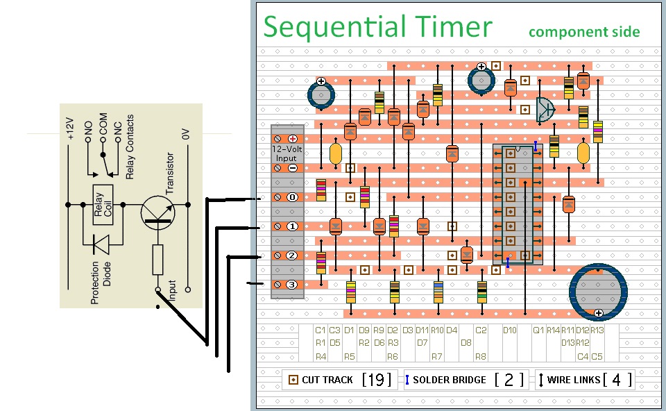
guys i need a 2 circuit the one is
when power applied the timer will trigger and the relay will remain off
when the timer runs out the relay will turn on and close the 2nd ciruit
and the 2nd circuit should b ON/OFF relay drive 4 times only and the ON/OFF
delay should be adjustable, after 4 time repeatation it should stopped
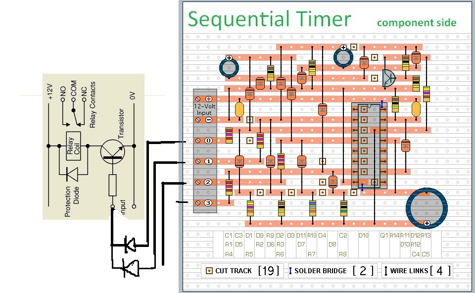
when power applied the timer will trigger and the relay will remain off
when the timer runs out the relay will turn on and close the 2nd ciruit
and the 2nd circuit should b ON/OFF relay drive 4 times only and the ON/OFF
delay should be adjustable, after 4 time repeatation it should stopped