gmorfeus
Junior Member level 1
Hi,
I am working on a device that uses M95 as GPRS modem. The problem I am experiencing is sudden strange behavior of my device. I have been developing it for 6 months now and it was working without any problems when connected to laboratory PS. As the device will be powered up by car 12V, I tested it a couple of days in my car. It was working just fine. Now when it is back to laboratory PS, the problem is that M95 shuts down when SIM pin is issued (so, when device connects to the GSM network). Well, sometimes that connecting to GSM network work well, but it shuts down on GPRS connection or on TCP/IP connect (so it's random). Strange in all this is that the device works OK when powered from battery. What I also notice is that when M95 is about to shut down, another LED connected to main micro-controller flickers. I think it is something with the NCP3170 regulator circuit but just can't conclude what exactly Have changed input capacitor and the NCP itself, but the problem is still present. I've done NCP design using their online utility and the measured output voltage (Reg. output on schematic) is 4.65V. On the Output of the PS circuit, voltage is 4.4V and that's inside permitted M95 supply voltage.
Don't know where else to look to find what might be the problem? Can a bad capacitor on output stage of DC-DC cause described problem?
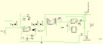
Schematic of complete power supply (DC-DC, battery protection, battery charging and switch PS from battery to DC-DC is in the attachment). The power trace to M95 is 2mm wide and just near M95, I have put:
Tantalum 470uF
ceramic: 100nF, 33pF, 10pF.
Thanks!
I am working on a device that uses M95 as GPRS modem. The problem I am experiencing is sudden strange behavior of my device. I have been developing it for 6 months now and it was working without any problems when connected to laboratory PS. As the device will be powered up by car 12V, I tested it a couple of days in my car. It was working just fine. Now when it is back to laboratory PS, the problem is that M95 shuts down when SIM pin is issued (so, when device connects to the GSM network). Well, sometimes that connecting to GSM network work well, but it shuts down on GPRS connection or on TCP/IP connect (so it's random). Strange in all this is that the device works OK when powered from battery. What I also notice is that when M95 is about to shut down, another LED connected to main micro-controller flickers. I think it is something with the NCP3170 regulator circuit but just can't conclude what exactly
Have changed input capacitor and the NCP itself, but the problem is still present. I've done NCP design using their online utility and the measured output voltage (Reg. output on schematic) is 4.65V. On the Output of the PS circuit, voltage is 4.4V and that's inside permitted M95 supply voltage.Don't know where else to look to find what might be the problem? Can a bad capacitor on output stage of DC-DC cause described problem?
Schematic of complete power supply (DC-DC, battery protection, battery charging and switch PS from battery to DC-DC is in the attachment). The power trace to M95 is 2mm wide and just near M95, I have put:
Tantalum 470uF
ceramic: 100nF, 33pF, 10pF.
Thanks!