Continue to Site

Welcome to EDAboard.com

Welcome to our site! EDAboard.com is an international Electronics Discussion Forum focused on EDA software, circuits, schematics, books, theory, papers, asic, pld, 8051, DSP, Network, RF, Analog Design, PCB, Service Manuals... and a whole lot more! To participate you need to register. Registration is free. Click here to register now.

[SOLVED] MWO - Funny looking values for voltages

Status
Not open for further replies.

golam.shaifullah

Newbie level 4
Joined
May 30, 2009
Messages
5
Helped
0
Reputation
0
Reaction score
0
Trophy points
1,281
Activity points
1,322
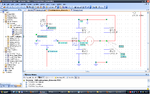
I'm trying to design a transimpedance amplifier to work from about 300kHz to 100 MHz, using the OPA657 from TI. A side project was to learn MWO, which I have never used. I tried to do a voltage annotation for all the nodes and don't quite like what I see... I should clarify that the OPA657 subcircuit was imported from spice into MWO's own format which was quite a mess! Had to spend a long time fixing it so that things seemed okay.. did manage to reproduce the small signal graphs from the datasheet. However, when I tried out the transimpedance from the datasheet, I got pretty disastrous results, then tried the voltage annotation business which gave me the results I have shown below. If anyone could cast some light on this I would be genuinely greatful!
Also attaching the AWR converted SPICE import of the OPA657. Advice welcome, including reading material. Have gone through most of the AWR literature, do not seem to find much help there.
Umm.. typically me; forgot to point out the problem. The OPA57 should run off a +-5 volt supply, but the node nearest the -5 volt shows 0 volts. Anybody?
 

Attachments

  • AWR_Spice_convOPA.txt
    14.2 KB · Views: 58
  • transimpedance.PNG
    transimpedance.PNG
    95.8 KB · Views: 106
Last edited:

Hello Golam,


its interesting upload ur AWR MWO file *.emp so tha some one will debug or comment on this funny results...
Did u setup the DC bias & also RF source inputs correctly!

---manju---
 

Hey manju,
As far as biasing goes, I have just followed the standard connections specified in the OPA657 datasheet; +-5 volts supply to respective pins with decoupling capacitors. As this is an OPAMP I wasn't aware of the need for biasing. Wouldn't the SPICE model behave analogous to the internal circuitry of the OPAMP?
For the RF inputs, I just used the standard port from MWO. Have not done anything else.
Will upload the .emp tomorrow as I'm away from work.
 

I hope some help is still around! I'm uploading the .emp file (in a zip file because edaboard uploader doesn't seem to recognise .emp). As I've said earlier, any advice is useful.
 

Attachments

  • ReducedStages.zip
    65.6 KB · Views: 79

Hey everybody,
Guess I am asking questions that are too mundane for this forum. Anyways, the story is I figured that this weird notation has something to do with MWOs internal ideas of Node voltages. The devices do seem to work fine regardless. I guess it is too much of an ask to get people to work on common platforms and platforms when they are looking to earn big bucks. Anyways, thanks a lot Manju for your suggestions. I am marking this thread closed now.
 

Status
Not open for further replies.

Part and Inventory Search

Welcome to EDABoard.com

Sponsor

Back
Top