moddinati
Newbie level 6
Hello,
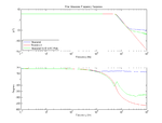
I'm designing a low-pass Butterworth filter using the multiple feedback topology. After building my prototype of my filter, there proved to be insufficient stopband attenuation due, to what I have been able to determine, to feed-through in the op-amp caused by parasitic capacitances between the op-amp input & the output. (The filter doesn't follow the theoretical -20 db/dec/pole in high frequencies and flattens out before sufficient attenuation has been reached.)
I'm trying to determine how I can reduce the effects of this feed-through capacitance. The best solution I have seen so far is to include a real, RC pole after the filter to provide the needed final attenuation. However, this solution will not work in this case as the values of the RC pole do not meet the requirements to properly drive the SAR ADC that follows.
I'm trying to determine which filter characteristics have the greatest effect on this feed-through and how it can be reduced (or pushed out to a farther frequency).
My question is:
1) Is it possible through proper selection/ addition of passive components to reduce the parasitic capacitance from Vin- to Vout?
2) What op-amp characteristics (maybe open-loop gain vs frequency?) determine where this feed-through zero is placed? How do I select an op-amp that will provide the proper attenuation to the frequencies desired?
If you have any ideas, or could point me to any resources, that may help, your help is appreciated.