Continue to Site

Welcome to EDAboard.com

Welcome to our site! EDAboard.com is an international Electronics Discussion Forum focused on EDA software, circuits, schematics, books, theory, papers, asic, pld, 8051, DSP, Network, RF, Analog Design, PCB, Service Manuals... and a whole lot more! To participate you need to register. Registration is free. Click here to register now.

[Moved] Schematic didn't work, Why?

Status
Not open for further replies.

kaSva

Junior Member level 1
Joined
Nov 26, 2013
Messages
19
Helped
0
Reputation
0
Reaction score
0
Trophy points
1
Activity points
136
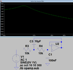
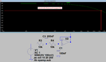
I get this schematic from industrial device. This schematic uses for 4-20mA sensor input on this device. I create same circuit on breadboard. But it didn't work. I used 741 op-amp. But Industrial device used 27L2C. Please tell me why didnt work?

27L2C datasheet https://www.ti.com/lit/ds/symlink/tlc27l2a.pdf

Circuit Schematic:

wbe6p4.jpg
 

Hi!

I'm not a anlog guy but I think ampop work with voltage signals and not current signals.
 

The opamps do not have a very important power supply.
The four 10k resistors on the first opamp cut the input to half then amplify it 2 times so these resistors are not needed. Then the first opamp can be a simple follower.
The second opamp is an odd filter with a peak.
 
What power supplies are you using (which are not shown)? The TL27L2C can operate from a single supply, the 741 requires a plus and minus supply.
 

I simulated the 2nd opamp's second-order Sallen-Key lowpass filter. It peaks at about 16Hz then slowly rolls off higher frequencies at 12dB per octave.
The poor SIM program clips the peak because maybe it will be very high. I tried a lower input level (100mV instead of 1V) and it made no difference.
 

Attachments

  • lowpass filter.png
    lowpass filter.png
    20.8 KB · Views: 98

YEs the reason the Op failed to get circuit to work , we agree is due lack of split supply on OA's with ground biased shunt. Mid V+ bias required for sgl. supply.

Sorry, I misread the 100nF as 100uF, which is why I thought something was wrong in Post #5

Now I see the same as you Audioguru.
My Sim showed LPF +14dB peak gain at 16.4Hz Q= 4.7

If the circuit is measuring 50Hz rectified current, then BOTH caps must be 0.1uF = 100nF then it becomes an optimal 2nd order 150Hz LPF with -3dB @100Hz.
 

If the circuit is measuring 50Hz rectified current, then BOTH caps must be 0.1uF = 100nF then it becomes an optimal 2nd order 150Hz LPF with -3dB @100Hz.
Then you have a droopy Bessel filter with a loss of almost 1dB at 50Hz. I would use 200nF as the feedback capacitor to make a Butterworth filter with the same -3dB 115Hz cutoff frequency as the Bessel filter but with a loss of only -0.2dB at 50Hz.
 

Attachments

  • Butterworth lowpass filter.png
    Butterworth lowpass filter.png
    25.6 KB · Views: 142

Thank you for all
 

Can you say "What's the I and II circuits doing?"

xfcgtd.jpg
 

"I" is an opamp follower. If the opamp has a high input resistance then the circuit has a 1M input resistance for DC and very low frequencies. It has no power supply.

"II" has an input attenuator. The 20k and 10 k resistors at the input reduce the signal to 1/3rd. The opamp has an adjustable input threshold voltage. It also has no power supply.
 
  • Like
Reactions: kaSva

    kaSva

    Points: 2
    Helpful Answer Positive Rating
Thank you Audioguru
 

The circuit is intended to filter a large DC signal with noise with filtered, clamped and attenuated output.

The input impedance to noise is 1k.

The 1st stage has a 10ms time constant with input connected and a 10 second decay time to 0 when disconnected.

The Transient Voltage Suppression (TVS) is to protect the device from over voltage.

Stage I is unity gain.
Stage II has a gain of 1/3*(1+1/2) = 0.5
 

I get this circuit from Industrial Device's(made in china) sensor input port(reading analog voltage). Can you analyse for me? and why using series two different filter(3rd op-amp(first order LPF) and 4th op-amp(second order)) ?

And 2nd and 3rd op-amp circuits was removed another sensor input (only using 1st and 4th op-amp circuits). Are these blocks(2. and 3. op-amps circuits) noteworthy contributes? Because i think to dont use these blocks

2l8w7dk.jpg
 
Last edited:

why using series two different filter(3rd op-amp(first order LPF) and 4th op-amp(second order)) ?
The third opamp has variable voltage gain. A Sallen-Key lowpass filter can be made 3rd-order but it will oscillate if it has voltage gain.
 

Status
Not open for further replies.

Similar threads

Part and Inventory Search

Welcome to EDABoard.com

Sponsor

Back
Top