reidbecker
Newbie level 4
Connection Problem: IC 74LS83A 4-Bit Binary Full Adder
Set-up Description
I am a volunteer in schools trying to create an electronics project for Middle School children titled "How A Computer Really, Really, Really Works," and am having difficulty getting the IC 4-bit adder to work. The setup I am using and the problems I am having are described below. I attached a picture of the setup and included a link to the Motorola 74LS83A data sheet. Any explanations, hopefully at a very fundamental level, would be appreciated.
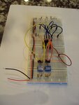
Four breadboards are connected with the + power rails connected via red cables and the – power rails connected with black cables. I used a multimeter to verify that all the power rails have power. I used two 4-bit Dip Switches (left for A input and right for B input) which were inserted into the E8-11 and E14-17 breadboard positions, respectively, and terminate on the F8-11 and F14-17 positions, respectively. I used a multimeter to verify continuity when the DIP switches are in the closed positions. The two DIP switches (input A and B) are connected to the IC pins as specified in the Motorola Connection Diagram which is attached; specifically: A1-Pin 10, A2-Pin 8, A3-Pin 3, A4-Pin 1, B1-Pin11, B2-Pin7, B3-Pin4, B4-Pin16.
There are five LED’s: Led1 (left most LED) is the one’s place, LED4 is in the 8’s place, and LED5 is the C4 Carryover place. The four ∑ output pins are connected using dark blue wires. The C4 (Pin14) is connected to LED5 with a white wire. The anode leads of each LED are connected to the IC pins as follows: LED1-Pin9, LED2-Pin6, LED3-Pin2, LED4-Pin15 and LED5-Pin14. Pin13 (C0) pinout is connected to the negative power rail with a black wire, as there is no carry-in value. Pin5 (VCC) is connected to the + Power Rail with a red wire. Pin12 (GND) is connected to the – Power Rail using a black wire.
The 4-bit DIP switches are in series with 100K Ohm resistors which in turn are connected to the + Power Rail. There are 10K Ohm resistors in series with the cathode side of the LED’s.
A Power Supply powers the circuits. The Power Supply delivers a constant voltage of 4V and maximum amperage of .3 mA. The emitter-collector circuits are lighting the LED’s and the measured amperage is .15 ma. If there were a circuit through the base pins, it would measure 39 micro-amps (I measured it via a multimeter with a simple circuit not through the IC’s).
I am not currently using an IC carrier to mount the IC onto the breadboard. This was ordered; however it will not be received from China for another 2-4 weeks. However, a multimeter continuity test verifies a good connection for each of the 16 IC pins to the breadboard. I have not used anti-static wrist straps.
Problem
When I turn on the power supply and all DIP switches are in the “off” position, all LED’s light. There is no amperage when measuring current going into any of the input A or B pins of the IC. There are no changes when I slide any of the DIP input switches (inputs A and B) to the “on” or “off” positions.
I have ordered two batches of 74LS83A and the results are the same.
A picture of the setup is attached. A pdf file of the 74LS83A is attached. Note this is a 4-Bit Binary Full Adder with Fast Carry.
A link to the Motorola data sheet for the 74LS83A is below:
http://pdf.datasheetcatalog.com/datasheet/motorola/SN74LS83D.pdf
Questions
1. Can you see any reason why I am getting incorrect results (i.e. all the LED’s are lit all the time)?
2. Can you suggest any way I can further test the IC with just a multimeter? I do not have access to an automated IC test system?
Set-up Description
I am a volunteer in schools trying to create an electronics project for Middle School children titled "How A Computer Really, Really, Really Works," and am having difficulty getting the IC 4-bit adder to work. The setup I am using and the problems I am having are described below. I attached a picture of the setup and included a link to the Motorola 74LS83A data sheet. Any explanations, hopefully at a very fundamental level, would be appreciated.
Four breadboards are connected with the + power rails connected via red cables and the – power rails connected with black cables. I used a multimeter to verify that all the power rails have power. I used two 4-bit Dip Switches (left for A input and right for B input) which were inserted into the E8-11 and E14-17 breadboard positions, respectively, and terminate on the F8-11 and F14-17 positions, respectively. I used a multimeter to verify continuity when the DIP switches are in the closed positions. The two DIP switches (input A and B) are connected to the IC pins as specified in the Motorola Connection Diagram which is attached; specifically: A1-Pin 10, A2-Pin 8, A3-Pin 3, A4-Pin 1, B1-Pin11, B2-Pin7, B3-Pin4, B4-Pin16.
There are five LED’s: Led1 (left most LED) is the one’s place, LED4 is in the 8’s place, and LED5 is the C4 Carryover place. The four ∑ output pins are connected using dark blue wires. The C4 (Pin14) is connected to LED5 with a white wire. The anode leads of each LED are connected to the IC pins as follows: LED1-Pin9, LED2-Pin6, LED3-Pin2, LED4-Pin15 and LED5-Pin14. Pin13 (C0) pinout is connected to the negative power rail with a black wire, as there is no carry-in value. Pin5 (VCC) is connected to the + Power Rail with a red wire. Pin12 (GND) is connected to the – Power Rail using a black wire.
The 4-bit DIP switches are in series with 100K Ohm resistors which in turn are connected to the + Power Rail. There are 10K Ohm resistors in series with the cathode side of the LED’s.
A Power Supply powers the circuits. The Power Supply delivers a constant voltage of 4V and maximum amperage of .3 mA. The emitter-collector circuits are lighting the LED’s and the measured amperage is .15 ma. If there were a circuit through the base pins, it would measure 39 micro-amps (I measured it via a multimeter with a simple circuit not through the IC’s).
I am not currently using an IC carrier to mount the IC onto the breadboard. This was ordered; however it will not be received from China for another 2-4 weeks. However, a multimeter continuity test verifies a good connection for each of the 16 IC pins to the breadboard. I have not used anti-static wrist straps.
Problem
When I turn on the power supply and all DIP switches are in the “off” position, all LED’s light. There is no amperage when measuring current going into any of the input A or B pins of the IC. There are no changes when I slide any of the DIP input switches (inputs A and B) to the “on” or “off” positions.
I have ordered two batches of 74LS83A and the results are the same.
A picture of the setup is attached. A pdf file of the 74LS83A is attached. Note this is a 4-Bit Binary Full Adder with Fast Carry.
A link to the Motorola data sheet for the 74LS83A is below:
http://pdf.datasheetcatalog.com/datasheet/motorola/SN74LS83D.pdf
Questions
1. Can you see any reason why I am getting incorrect results (i.e. all the LED’s are lit all the time)?
2. Can you suggest any way I can further test the IC with just a multimeter? I do not have access to an automated IC test system?