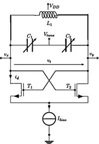
Re: LC tank oscillator. How can I choose the ratio L and C ?
Warpspeed,
(i) please, could you clarify? it is not clear how the LC ratio will defines the loaded Q? Capacitor implemented as MiM cap or Inductor, which of these have the worse Q? I guess is the inductor.
But I do not understand why decreasing L will improve the LC-tank Q.
Any tuned circuit is going to have some losses.
Those could be due to series resistance in the components themselves, or shunt resistance of either some load, or whatever drives the tuned circuit.
You need to look at the entire system, the circuitry around the tuned circuit, as well as the components themselves within the tuned circuit, as well as the operating frequency and intended application.
For least phase noise, you definitely need the highest Q circuit with absolutely minimal losses. Without knowing the circuit topology, the impedances or loadings involved, its not possible to suggest an optimum LC ratio.
For instance, inductors may be either the most lossy, or least lossy part of the circuit, it depends on a whole lot of other factors.
Likewise with capacitor types, as well as values.
All you have told us about this is that it is a traditional tuned tank circuit.
The frequency also has a strong bearing on selecting components.
An air cored inductor would very likely give lowest losses at higher frequencies.
But at much lower frequencies some kind of magnetic core will greatly reduce the number of turns and may or may not reduce overall losses, because the core material itself introduces new loss mechanisms.
At 10Hz a huge laminated iron core might be expected to produce the lowest loss inductor.
Another problem quite apart from phase noise is frequency stability.
That may or may not be of even greater importance.